(!)Due to Microsoft's end of support for Internet Explorer 11 on 15/06/2022, this site does not support the recommended environment.
- [Announcement] MISUMI Malaysia website new user interface. Clearer navigation, easy product search and more. Explore now! May contact us at (60) 3 7890 6399 for any inquiries.
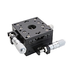
XY-Axis Manual Stages, Cross Roller Guide (Part Numbers)


- Volume Discount
- XY-Axis Manual Stages, Cross Roller Guide type, E-XYPG series from MISUMI.
- This is an economy item; The price is cheaper than the MISUMI standard product.
- 3 stage sizes are available, 40, 60 and 80.
- Load capacity can be selected from 17.6 N to 93.1 N.
- The minimum scale for reading is 10 μm.
- 8 alteration options for changing the position of the micrometer knob are available.
Part Number
Configured Part Number is shown.

| Type | Type |  Material Material |  Surface treatment Surface treatment | Travel distance (mm) | Load capacity (N) | Straightness |
| E-XYPG | Standard version | Aluminum alloy | Black anodized finish | ±3.25 to ±25 | 9.8 to 180.3 | Within 20µm |
| E-XYPBG | Thin type |
| Alterations | Change the position of the micrometer knob | ||||
| Spec. | Center | Center left/right reversed | Side left/right reversed | Side vertical reversal | Left/right or vertical reversal |
| Code | A | AR | CR | CZ | CZR |
| Alterations | Change the position of the micrometer knob | ||||
| Spec. | Disc clamping | Opposed clamping | No micrometer knob | ||
| Code | H | P | MN | ||
| Type | Stage surface (mm) | Travel distance (mm) | Load Capacity (N) Horizontal | Straightness (µm) | Minimum reading (µm) | Weight (kg) | |
 Type Type |  No. No. | ||||||
| E-XYPG | 20 | 20 × 20 | ±3.25 | 9.8 | Within 20 | 10 | 0.06 |
| 25 | 25 × 25 | 0.064 | |||||
| 40 | 40 × 40 | ±6.5 | 17.6 | 0.3 | |||
| 60 | 60 × 60 | 44.1 | 0.52 | ||||
| 80 | 80 × 80 | ±12.5 | 93.1 | 1 | |||
| 100 | 100 × 100 | 140.1 | 1.4 | ||||
| 120 | 120 × 120 | ±25 | 180.3 | 3.2 | |||
| E-XYPBG | 30 | 30 × 30 | ±3.25 | 14.7 | 0.09 | ||
| 50 | 50 × 50 | ±6.5 | 39.2 | 0.4 | |||
| 70 | 70 × 70 | 58.8 | 0.76 | ||||
| 90 | 90 × 90 | ±12.5 | 117.6 | 0.8 | |||
■ Travel distance
The catalog drawing dimensions are based on a stroke of 0 mm. Using this as a reference, the distance moved in the left and right directions is the travel distance.
■ Load capacity
Refers to the force that the slide table can withstand when the workpiece's center of gravity is located at the center of the slide table, measured in N. If used beyond the load capacity, the slide table may not operate smoothly or may become stuck. When installing the linear motion slide table vertically or upside down, the accuracy may be less than the values indicated in the product catalog. Please take note.
■ Straightness
The maximum deviation of the slide table from the ideal movement axis (the straight line connecting the start and end points, shown as the red line in the diagram below; the black line represents the actual movement path) during full-stroke movement. Measurement method: Place a dial indicator on the slide table with the pointer touching the reference block. Move the slide table through its full stroke and measure the maximum displacement, which is the straightness.


Feature 2: Achieves a low price by simplifying the structure and improving the manufacturing process.
Feature 3: Supports various additional machining options to meet installation requirements in different situations.
Feature 4: Improved clamping mechanism provides greater holding force for the slide table compared to the standard clamping mechanism.
When installing the slide table onto the base, the installation is generally performed by moving the slide table surface. Please refer to the diagram below.

 The above diagram is for installation example demonstration only. For detailed shapes and specifications of the slide table, please refer to the respective product catalog or 3D data.
■ Installation orientation
| Diagram |  |  |  |  |
| Installation orientation | Horizontal | Inverted | Side-mounted horizontal | Side-mounted vertical |
| Load resistance characteristics | ○ | ○ | △ | △ |
Horizontal, inverted, side horizontal, or side vertical installation can be selected. For other installation methods, please pay special attention.Depending on the installation orientation, load capacity and accuracy may vary significantly.○: Same load capacity as horizontal installation.△: Approximately one-third of the horizontal load capacity is the general standard. If the product catalog lists the vertical load capacity, please give priority to the catalog.■Vertical Use of X-Axis Stage
When using the X-axis stage vertically, please pay attention to the feed direction and avoid aligning it with the direction of gravity.
When using a micrometer knob type stage, please note that the stage is reset by a tension spring. If the applied force exceeds the spring load, the stage platform may drop. In such cases, additional processing can be selected as a solution.
| Incorrect usage | Correct usage |
| (Generally) If the applied force exceeds the tension load of the spring, the stage platform may fall due to insufficient load capacity. | After selecting the additional machining to change the micrometer knob position, the stage surface will not drop even when used vertically. |
 |  |
Please avoid applying loads in the vertical direction that exceed the load capacity.Recommended operating environment: 10–50°C, 20–70% RH (no condensation)
Accuracy-guaranteed environment: 22±5°C, 20–70% RH (no condensation)
■ Guide mechanism
This stage uses a crossed roller guide as the guiding mechanism. Please apply lubricant as needed according to the operating conditions to prevent reduced lubrication or aging, which could shorten the service life of the crossed roller guide.
■ Clamping mechanism
(1) The clamping mechanism of the stage is fixed by the friction force generated by tightening the screws. Therefore, if an external force exceeding the friction force of the clamping mechanism is applied, the stage will move. Please take appropriate measures during use to prevent the stage surface from moving. If additional clamping reinforcement is required, you can choose either disc clamping or opposed clamping.
(2) Holding force refers to the amount of force that keeps the stage surface from moving when clamped. Since the maximum holding force varies with changes in tightening torque, please ensure a sufficiently large safety factor in your design.
■ Feed Mechanism
A stage equipped with a micrometer knob, as shown in the figure below, is generally referred to as the standard type. The installation space, installation orientation, and operation method can be freely selected. However, due to the structure of the product, there are some models where the installation position of the micrometer knob cannot be changed. For details, please refer to the [Additional Machining] section at the bottom of each product page.

■ Flatness of the mounting surface
The upper and lower slide table surfaces may become deformed due to differences in the flatness of the mounting surface. Deformation of the slide table surface may result in gaps, inability to achieve the specified preload causing looseness, or excessive preload leading to poor sliding performance. Therefore, it is recommended to maintain the flatness of the mounting surface at around 5 micrometers.

| Electronics/Home Appliances | Automotive | Medical | ||
 |  |  | ||
| Smartphones | Semiconductors | Lithium batteries | ||
 |  |  |
| Economical Electric Slide Table X-Axis | Economical Electric Slide Table XY-Axis | Economical Electric Slide Table Z-Axis | ||
 |  |  | ||
| Representative model: C-XMBS420-L-A-2 | Representative model: C-XYMBS420-L-A-2 | Representative model: C-ZMBS420-L-A-2 | ||
| Advantage: Low cost, fast delivery | Advantage: Low cost, fast delivery | Advantage: Low cost, fast delivery |
Part Number
CAD Data download and 3D preview are not available because the part number has not yet been determined.
- *In order to open the CAD Data download and 3D preview screen, the part number must be fixed.
- Please confirm the part number from "Specification / Dimension"on the left side, and then perform the CAD Data Download / 3D Preview operation.
| Part Number | Standard Unit Price | Minimum order quantity | Volume Discount | Days to Ship | Load Capacity (Range Selectable) (N) | Table Size (Length) L (Range Selectable) (mm) | Table Size (Width) W (Range Selectable) (mm) | Travel Distance (X-Axis) (Range Selectable) (mm) | Travel Distance (Y-Axis) (Range Selectable) (mm) | Table Size (Thickness) H (Range Selectable) (mm) | Table Size (Length) L (mm) | Table Size (Width) W (mm) | Load Capacity (N) | Travel Distance (X-Axis) (mm) | Travel Distance (Y-Axis) (mm) | Table Dimensions | Alteration | Travel distance (mm) |
|---|---|---|---|---|---|---|---|---|---|---|---|---|---|---|---|---|---|---|
MYR 426.34 | 1 Piece(s) | 16 Day(s) | - | - | - | - | - | - | 30 | 30 | 14.7 | - | - | - | Standard Type | ±3.25 | ||
MYR 426.34 | 1 Piece(s) | 16 Day(s) | - | - | - | - | - | - | 30 | 30 | 14.7 | - | - | - | A [Change knob position: center] | ±3.25 | ||
MYR 426.34 | 1 Piece(s) | 16 Day(s) | - | - | - | - | - | - | 30 | 30 | 14.7 | - | - | - | AR [Change knob position: center, left/right reversed] | ±3.25 | ||
MYR 464.63 | 1 Piece(s) | 16 Day(s) | - | - | - | - | - | - | 50 | 50 | 39.2 | - | - | - | Standard Type | ±6.5 | ||
MYR 464.63 | 1 Piece(s) | 16 Day(s) | - | - | - | - | - | - | 50 | 50 | 39.2 | - | - | - | A [Change knob position: center] | ±6.5 | ||
MYR 464.63 | 1 Piece(s) | 16 Day(s) | - | - | - | - | - | - | 50 | 50 | 39.2 | - | - | - | AR [Change knob position: center, left/right reversed] | ±6.5 | ||
MYR 691.46 | 1 Piece(s) | 16 Day(s) | - | - | - | - | - | - | 70 | 70 | 58.8 | - | - | - | Standard Type | ±6.5 | ||
MYR 691.46 | 1 Piece(s) | 16 Day(s) | - | - | - | - | - | - | 70 | 70 | 58.8 | - | - | - | A [Change knob position: center] | ±6.5 | ||
MYR 691.46 | 1 Piece(s) | 16 Day(s) | - | - | - | - | - | - | 70 | 70 | 58.8 | - | - | - | AR [Change knob position: center, left/right reversed] | ±6.5 | ||
MYR 720.92 | 1 Piece(s) | 16 Day(s) | - | - | - | - | - | - | 90 | 90 | 117.6 | - | - | - | Standard Type | ±12.5 | ||
MYR 720.92 | 1 Piece(s) | 16 Day(s) | - | - | - | - | - | - | 90 | 90 | 117.6 | - | - | - | A [Change knob position: center] | ±12.5 | ||
MYR 720.92 | 1 Piece(s) | 16 Day(s) | - | - | - | - | - | - | 90 | 90 | 117.6 | - | - | - | AR [Change knob position: center, left/right reversed] | ±12.5 | ||
MYR 420.45 | 1 Piece(s) | 16 Day(s) | - | - | - | - | - | - | 20 | 20 | 9.8 | - | - | - | Standard Type | ±3.25 | ||
MYR 420.45 | 1 Piece(s) | 16 Day(s) | - | - | - | - | - | - | 20 | 20 | 9.8 | - | - | - | CR [Change knob position: left and right sides reversed] | ±3.25 | ||
MYR 426.34 | 1 Piece(s) | 16 Day(s) | - | - | - | - | - | - | 25 | 25 | 9.8 | - | - | - | Standard Type | ±3.25 | ||
MYR 426.34 | 1 Piece(s) | 16 Day(s) | - | - | - | - | - | - | 25 | 25 | 9.8 | - | - | - | CR [Change knob position: left and right sides reversed] | ±3.25 | ||
MYR 490.80 | 1 Piece(s) | Available | 10 Day(s) | 5.1~30.0 | 26~40 | 26~40 | Up to ±10mm | Up to ±10mm | 35.1~40 | 40 | 40 | 17.6 | ±6.5 | ±6.5 | 40 | Standard Type | ±6.5 | |
MYR 490.80 | 1 Piece(s) | Available | 1 Day(s) | 5.1~30.0 | 26~40 | 26~40 | Up to ±10mm | Up to ±10mm | 35.1~40 | 40 | 40 | 17.6 | ±6.5 | ±6.5 | 40 | A [Change knob position: center] | ±6.5 | |
MYR 490.80 | 1 Piece(s) | Available | 1 Day(s) | 5.1~30.0 | 26~40 | 26~40 | Up to ±10mm | Up to ±10mm | 35.1~40 | 40 | 40 | 17.6 | ±6.5 | ±6.5 | 40 | AR [Change knob position: center, left/right reversed] | ±6.5 | |
MYR 490.80 | 1 Piece(s) | Available | 1 Day(s) | 5.1~30.0 | 26~40 | 26~40 | Up to ±10mm | Up to ±10mm | 35.1~40 | 40 | 40 | 17.6 | ±6.5 | ±6.5 | 40 | CR [Change knob position: left and right sides reversed] | ±6.5 | |
MYR 490.80 | 1 Piece(s) | Available | 1 Day(s) | 5.1~30.0 | 26~40 | 26~40 | Up to ±10mm | Up to ±10mm | 35.1~40 | 40 | 40 | 17.6 | ±6.5 | ±6.5 | 40 | CZ [Change knob position: Reverse up and down on the side] | ±6.5 | |
MYR 490.80 | 1 Piece(s) | Available | 10 Day(s) | 5.1~30.0 | 26~40 | 26~40 | Up to ±10mm | Up to ±10mm | 35.1~40 | 40 | 40 | 17.6 | ±6.5 | ±6.5 | 40 | CZR [Change knob position: Side left/right / Up/down reverse direction] | ±6.5 | |
MYR 490.80 | 1 Piece(s) | Available | 10 Day(s) | 5.1~30.0 | 26~40 | 26~40 | Up to ±10mm | Up to ±10mm | 35.1~40 | 40 | 40 | 17.6 | ±6.5 | ±6.5 | 40 | H [Clamping Enhancement: Disc Clamping] | ±6.5 | |
MYR 387.36 | 1 Piece(s) | Available | 10 Day(s) | 5.1~30.0 | 26~40 | 26~40 | Up to ±10mm | Up to ±10mm | 35.1~40 | 40 | 40 | 17.6 | ±6.5 | ±6.5 | 40 | MN [No Micrometer Knob] | ±6.5 | |
MYR 490.80 | 1 Piece(s) | Available | 10 Day(s) | 5.1~30.0 | 26~40 | 26~40 | Up to ±10mm | Up to ±10mm | 35.1~40 | 40 | 40 | 17.6 | ±6.5 | ±6.5 | 40 | P [Clamping Enhancement: Opposed Clamping] | ±6.5 | |
MYR 531.20 | 1 Piece(s) | Available | 8 Day(s) | 30.1~50 | 41~60 | 41~60 | Up to ±10mm | Up to ±10mm | 35.1~40 | 60 | 60 | 44.1 | ±6.5 | ±6.5 | 60 | Standard Type | ±6.5 | |
MYR 531.20 | 1 Piece(s) | Available | 1 Day(s) | 30.1~50 | 41~60 | 41~60 | Up to ±10mm | Up to ±10mm | 35.1~40 | 60 | 60 | 44.1 | ±6.5 | ±6.5 | 60 | A [Change knob position: center] | ±6.5 | |
MYR 531.20 | 1 Piece(s) | Available | 10 Day(s) | 30.1~50 | 41~60 | 41~60 | Up to ±10mm | Up to ±10mm | 35.1~40 | 60 | 60 | 44.1 | ±6.5 | ±6.5 | 60 | AR [Change knob position: center, left/right reversed] | ±6.5 | |
MYR 531.20 | 1 Piece(s) | Available | 10 Day(s) | 30.1~50 | 41~60 | 41~60 | Up to ±10mm | Up to ±10mm | 35.1~40 | 60 | 60 | 44.1 | ±6.5 | ±6.5 | 60 | CR [Change knob position: left and right sides reversed] | ±6.5 | |
MYR 531.20 | 1 Piece(s) | Available | 1 Day(s) | 30.1~50 | 41~60 | 41~60 | Up to ±10mm | Up to ±10mm | 35.1~40 | 60 | 60 | 44.1 | ±6.5 | ±6.5 | 60 | CZ [Change knob position: Reverse up and down on the side] | ±6.5 | |
MYR 531.20 | 1 Piece(s) | Available | 10 Day(s) | 30.1~50 | 41~60 | 41~60 | Up to ±10mm | Up to ±10mm | 35.1~40 | 60 | 60 | 44.1 | ±6.5 | ±6.5 | 60 | CZR [Change knob position: Side left/right / Up/down reverse direction] | ±6.5 | |
MYR 531.20 | 1 Piece(s) | Available | 10 Day(s) | 30.1~50 | 41~60 | 41~60 | Up to ±10mm | Up to ±10mm | 35.1~40 | 60 | 60 | 44.1 | ±6.5 | ±6.5 | 60 | H [Clamping Enhancement: Disc Clamping] | ±6.5 | |
MYR 427.80 | 1 Piece(s) | Available | 10 Day(s) | 30.1~50 | 41~60 | 41~60 | Up to ±10mm | Up to ±10mm | 35.1~40 | 60 | 60 | 44.1 | ±6.5 | ±6.5 | 60 | MN [No Micrometer Knob] | ±6.5 | |
MYR 531.20 | 1 Piece(s) | Available | 10 Day(s) | 30.1~50 | 41~60 | 41~60 | Up to ±10mm | Up to ±10mm | 35.1~40 | 60 | 60 | 44.1 | ±6.5 | ±6.5 | 60 | P [Clamping Enhancement: Opposed Clamping] | ±6.5 | |
MYR 821.46 | 1 Piece(s) | Available | 1 Day(s) | 50.1~100 | 61~90 | 61~90 | ±10 to 30mm | ±10 to 30mm | 35.1~40 | 80 | 80 | 93.1 | ±12.5 | ±12.5 | 80 | Standard Type | ±12.5 | |
MYR 821.46 | 1 Piece(s) | Available | 1 Day(s) | 50.1~100 | 61~90 | 61~90 | ±10 to 30mm | ±10 to 30mm | 35.1~40 | 80 | 80 | 93.1 | ±12.5 | ±12.5 | 80 | A [Change knob position: center] | ±12.5 | |
MYR 821.46 | 1 Piece(s) | Available | 10 Day(s) | 50.1~100 | 61~90 | 61~90 | ±10 to 30mm | ±10 to 30mm | 35.1~40 | 80 | 80 | 93.1 | ±12.5 | ±12.5 | 80 | AR [Change knob position: center, left/right reversed] | ±12.5 | |
MYR 821.46 | 1 Piece(s) | Available | 6 Day(s) | 50.1~100 | 61~90 | 61~90 | ±10 to 30mm | ±10 to 30mm | 35.1~40 | 80 | 80 | 93.1 | ±12.5 | ±12.5 | 80 | CR [Change knob position: left and right sides reversed] | ±12.5 | |
MYR 821.46 | 1 Piece(s) | Available | 10 Day(s) | 50.1~100 | 61~90 | 61~90 | ±10 to 30mm | ±10 to 30mm | 35.1~40 | 80 | 80 | 93.1 | ±12.5 | ±12.5 | 80 | CZ [Change knob position: Reverse up and down on the side] | ±12.5 | |
MYR 821.46 | 1 Piece(s) | Available | 10 Day(s) | 50.1~100 | 61~90 | 61~90 | ±10 to 30mm | ±10 to 30mm | 35.1~40 | 80 | 80 | 93.1 | ±12.5 | ±12.5 | 80 | CZR [Change knob position: Side left/right / Up/down reverse direction] | ±12.5 | |
MYR 821.46 | 1 Piece(s) | Available | 10 Day(s) | 50.1~100 | 61~90 | 61~90 | ±10 to 30mm | ±10 to 30mm | 35.1~40 | 80 | 80 | 93.1 | ±12.5 | ±12.5 | 80 | H [Clamping Enhancement: Disc Clamping] | ±12.5 | |
MYR 718.06 | 1 Piece(s) | Available | 10 Day(s) | 50.1~100 | 61~90 | 61~90 | ±10 to 30mm | ±10 to 30mm | 35.1~40 | 80 | 80 | 93.1 | ±12.5 | ±12.5 | 80 | MN [No Micrometer Knob] | ±12.5 | |
MYR 821.46 | 1 Piece(s) | Available | 10 Day(s) | 50.1~100 | 61~90 | 61~90 | ±10 to 30mm | ±10 to 30mm | 35.1~40 | 80 | 80 | 93.1 | ±12.5 | ±12.5 | 80 | P [Clamping Enhancement: Opposed Clamping] | ±12.5 | |
MYR 853.48 | 1 Piece(s) | 16 Day(s) | - | - | - | - | - | - | 100 | 100 | 140.1 | - | - | - | Standard Type | ±12.5 | ||
MYR 853.48 | 1 Piece(s) | 16 Day(s) | - | - | - | - | - | - | 100 | 100 | 140.1 | - | - | - | A [Change knob position: center] | ±12.5 | ||
MYR 853.48 | 1 Piece(s) | 16 Day(s) | - | - | - | - | - | - | 100 | 100 | 140.1 | - | - | - | AR [Change knob position: center, left/right reversed] | ±12.5 | ||
MYR 853.48 | 1 Piece(s) | 16 Day(s) | - | - | - | - | - | - | 100 | 100 | 140.1 | - | - | - | CR [Change knob position: left and right sides reversed] | ±12.5 | ||
MYR 1,442.63 | 1 Piece(s) | 16 Day(s) | - | - | - | - | - | - | 120 | 120 | 180.3 | - | - | - | Standard Type | ±25 | ||
MYR 1,442.63 | 1 Piece(s) | 16 Day(s) | - | - | - | - | - | - | 120 | 120 | 180.3 | - | - | - | CR [Change knob position: left and right sides reversed] | ±25 |
Loading...
Basic Information
| Table (Details) | Aluminum Alloy | Feeding Method | Micrometer Head + Coarse Feed Knob | Travel Guide (Details) | Cross Roller |
|---|---|---|---|---|---|
| Table Surface Treatment | Black Anodize | Through Hole (Table Center Hole) | Not Provided | Table Straightness(µm) | 20 |
Specification/Dimensions
-
Load Capacity (Range Selectable)(N)
- 5.1~30.0
- 30.1~50
- 50.1~100
-
Table Size (Length) L (Range Selectable)(mm)
-
Table Size (Width) W (Range Selectable)(mm)
-
Travel Distance (X-Axis) (Range Selectable)(mm)
-
Travel Distance (Y-Axis) (Range Selectable)(mm)
-
Table Size (Thickness) H (Range Selectable)(mm)
-
Table Size (Length) L(mm)
-
Table Size (Width) W(mm)
-
Load Capacity(N)
-
Travel Distance (X-Axis)(mm)
-
Travel Distance (Y-Axis)(mm)
-
Table Dimensions
- 40
- 60
- 80
-
Alteration
- A [Change knob position: center]
- AR [Change knob position: center, left/right reversed]
- CR [Change knob position: left and right sides reversed]
- CZ [Change knob position: Reverse up and down on the side]
- CZR [Change knob position: Side left/right / Up/down reverse direction]
- H [Clamping Enhancement: Disc Clamping]
- MN [No Micrometer Knob]
- P [Clamping Enhancement: Opposed Clamping]
- Standard Type
-
Travel distance(mm)
- ±3.25
- ±6.5
- ±12.5
- ±25
-
CAD
- 2D
- 3D
Days to Ship
-
- All
- 1 Day(s) or Less
- 6 Day(s) or Less
- 8 Day(s) or Less
- 10 Day(s) or Less
- 16 Day(s) or Less
Specify Alterations
- The specifications and dimensions of some parts may not be fully covered. For exact details, refer to manufacturer catalogs .
Frequently asked question (FAQ)
- Question: What does a micrometer knob-type positioning stage with a travel distance of ±XX mean?
- Answer: The travel ±XXmm means how many millimeters can be moved in each direction, left and right or up and down, with the middle of the full travel of the micrometer knob as the base point.
- Question: What is the reset method of the micrometer knob type manual positioning stage? What should be paid attention to in use?
- Answer: The micrometer knob type manual positioning stage is reset by means of an extension spring. If the applied load is greater than the spring load, the positioning stage surface may not reset properly or the spring may be damaged directly, so take care when using it.
- Question: Can the positioning stage be mounted vertically? What should be paid attention to?
- Answer: Yes, it can. However, attention should be paid that the load capacity is about 1/3 of that for horizontal installation; and that the feed direction should not be the same as gravity direction, because if the applied force is greater than the spring load, the positioning stage surface may not be able to support the weight and may fall.
- Question: Can manual positioning stage products be used upside down?
- Answer: All except dovetail products. Dovetail products are strictly forbidden to be used upside down.
- Question: Is it possible to freely assemble the XY type positioning stage without the dimension or travel I want?
- Answer: Yes, it is.
Additional Products in this Category
- [High Precision] Linear Ball - Micrometer Head / Feed Screw
- [High Precision] XY-Axis Linear Ball Slide - Coarse / Fine Micrometer Head
- [High Precision] Cross Roller - Low Profile
- [High Precision] XY-Axis Dovetail Slide, Feed Screw - Extended Knob (Lead 4.2mm)
- XY-Axis Aluminum Cross Roller Stage TAM
- Manual XY Axis, Dovetail Groove Gear Rack Stage 40 × 40 / 40 × 60 / 40 × 80 / 40 × 100 / 40 × 120 / 40 × 140 [D2-4]
- Semi-Order Stage (Handle Extension Type XY Axis)
- Dovetail Slide Stage XYMB Series Square Type
Tech Support
- Credit Card
- Bank Transfer
Social Media
MISUMI Contact
Copyright © MISUMI Corporation All Rights Reserved.
How can we improve?
How can we improve?
While we are not able to respond directly to comments submitted in this form, the information will be reviewed for future improvement.
Customer Privacy Policy
Thank you for your cooperation.
While we are not able to respond directly to comments submitted in this form, the information will be reviewed for future improvement.
Please use the inquiry form.
Customer Privacy Policy