(!)Due to Microsoft's end of support for Internet Explorer 11 on 15/06/2022, this site does not support the recommended environment.
- [Announcement] MISUMI Malaysia website new user interface. Clearer navigation, easy product search and more. Explore now! May contact us at (60) 3 7890 6399 for any inquiries.
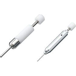
Dedicated Extraction Tool for CE01-Series Contacts
Click this image to zoom it.
Move the mouse over the image to zoom
- Volume Discount
[Specifications]·An extraction tool by CE01 contact size · Operating temperature range: −55°C to +125°C

·Extract using the dedicated tools.
Part Number
Configured Part Number is shown.
Specifications

| Model | Compatible Contact | Type | Weight g |
| 357J-12609-CE01 | CE01-#8P-C1M | Male Contact | 75 |
| CE01-#8S-C1M | Female Contact | ||
| CE01-#8P-C2M | Male Contact | ||
| CE01-#8S-C2M | Female Contact | ||
| 357J-12612-CE01 | CE01-#12P-C1M | Male Contact | 70 |
| CE01-#12S-C1M | Female Contact | ||
| 357J-12615-CE01 | CE01-#16P-C1416 | Male Contact | 65 |
| CE01-#16S-C1416 | Female Contact | ||
| CE01-#16P-C1620 | Male Contact | ||
| CE01-#16S-C1620 | Female Contact | ||
| CE01-#16P-C2024 | Male Contact | ||
| CE01-#16S-C2024 | Female Contact | ||
| 357J-13979-CE01 | CE01-#20P-C1 | Male Contact | 40 |
| CE01-#20P-C1 | Female Contact | ||
| CE01-#20P-C2 | Male Contact | ||
| CE01-#20P-C2 | Female Contact |
More Information
| Part Number |
|---|
| 357J-12612-CE01 |
| 357J-12615-CE01 |
| Part Number | Standard Unit Price | Minimum order quantity | Volume Discount | Days to Ship | Applicable wire size (AWG) |
|---|---|---|---|---|---|
MYR 1,311.51 | 1 Piece(s) | Available | 4 Day(s) or more | 12 ~ 16 | |
MYR 1,316.27 | 1 Piece(s) | Available | 4 Day(s) or more | 14 ~ 24 |
Loading...
Protection Circuit Connection Structural Diagram

About Compatible Products
NB01 connectors, CE01 connectors, and JL05 connectors are compatible with each other.Combination Method


Material / Finish
| Item | Materials | Finish |
|---|---|---|
| Shell (Body) | Aluminum Alloy | Black Chromate Treatment |
| Insulator | Polyester Resin | UL94V-0, Gray |
| Contact | Copper Alloy | Silver Plating |
| O-ring | Nitrile Rubber | Black |
| Coupling Nut | Aluminum Alloy | Black Chromate Treatment |
| Earth Lug | Steel Alloy | Silver Plating |
| Rear Gasket for Flange | Chloroprene Rubber | Black |
Electrical and Mechanical Properties, Compatible Wires
| Item | Characteristics | |||||||
|---|---|---|---|---|---|---|---|---|
| Rated Current | Contact Size | #20 | #16 | #12 | #8 | |||
| Maximum Value per 1 Piece | 5 A | 13 A | 23 A | 46 A | ||||
| Rated Voltage | Rating Classification | AC (r.m.s) | DC | |||||
| INST | 200 | 250 | ||||||
| A | 500 | 700 | ||||||
| D | 900 | 1,250 | ||||||
| Withstand Voltage | INST | 1,000 VAC (r.m.s) 1 minute | ||||||
| A | 2,000 VAC (r.m.s) 1 minute | |||||||
| D | 2,800 VAC (r.m.s) 1 minute | |||||||
| Insulation Resistance | 5,000 MΩ or more at 500 VDC | |||||||
| Contact Resistance | Contact Size | #20 | #16 | #12 | #8 | |||
| mΩ or less | 8 | 4 | 2 | 0.6 | ||||
| Operating Temperature Range | -55°C ~ +125°C | |||||||
| Waterproofing | IP67 Equivalent | |||||||
| Humidity | Relative Humidity 95% or less | |||||||
| Service Life | 500 Insertions and Removals | |||||||
| NB01 (Solder Type) Compatible Wires (Note 2) |
Contact Size | #16 | #12 | #8 | ||||
| Conductor Cross-sectional Area | 0.75 mm2 or less | 3.5 mm2 or less | 8 mm2 or less | |||||
| AWG Size | 18 or less | 12 or less | 8 or less | |||||
(Note 1) Rated voltage and voltage resistance are shown with rating classification symbols (INST, A; D). Refer as well to the table below.
Contact Arrangement Diagram
| Number of Contacts | 4 | 5 | 7 | 7 | 8 |
|---|---|---|---|---|---|
| Arrangement No. | 22-22 | 18-11 | 20-15 | 24-10 | 22-23 |
| Contact Size | #8 | #12 | #12 | #8 | #12 |
| Contact Arrangement (Note 1) (Note 2) |
 |
 |
 |
 |
 |
| Rating Classification | A | A | A | A | D (4), A (Others) |
| Number of Contacts | 10 | 17 | 19 | 19 | 24 |
|---|---|---|---|---|---|
| Arrangement No. | 18-1 | 20-29 | 18-19A | 22-14 | 24-28 |
| Contact Size | #16 | #16 | #20 | #16 | #16 |
| Contact Arrangement (Note 1) (Note 2) |
 |
 |
 |
 |
 |
| Rating Classification | A (3, 5, 6, 8), INST (Others) |
A | INST | A | INST |
| Number of Contacts | 30 | 37 | 52 | 73 |
| Arrangement No. | 20-30A | 28-21 | 24-52A | 28-73A |
| Contact Size | #20 | #16 | #20 | #20 |
| Contact Arrangement (Note 1) (Note 2) |
 |
 |
 |
 |
| Rating Classification | INST | A | INST | INST |
|---|
(Note 1) View from the male (pin) connector coupling surface.
(Note 2) The ○ in the arrangement table shows the earth terminals (for protection of terminal connections).
Panel Cut Size Drawing

| Compatible Shell Size |
φA ±0.5 |
φB +0.2 -0 |
C ±0.13 |
Mounting Screws (Reference) | Rear Mounting Panel Thickness Limit |
|
|---|---|---|---|---|---|---|
| Inch Screws | Metric Screws | |||||
| 18 | 30.2 | 3.3 | 26.97 | #4-40 | M3 | 3.0 or less |
| 20 | 34.9 | 3.3 | 29.36 | #4-40 | M3 | |
| 22 | 36.6 | 3.3 | 31.75 | #4-40 | M3 | |
| 24 | 39.7 | 4.3 | 34.92 | #6-32 | M4 | |
| 28 | 46.1 | 4.3 | 39.67 | #6-32 | M4 | |
Basic Information
| Applicable Type | CE Connector | Applicable type | CE01 Connector | Product classification | Extraction Tool |
|---|
- The specifications and dimensions of some parts may not be fully covered. For exact details, refer to manufacturer catalogs .
Additional Products in this Category
- Dynamic Connector Removal Tools (D5200 Series)
- Removal Tools For SM Connectors
- Contact Extraction Tool for Mini Universal MATE-N-LOK
- Extraction Jig for H.FL Series
- Terminal Extraction Jig for HIF3B Series
- Terminal Extraction Jig for QR/P Series
- Extraction Jig For U.FL Series
- Round Waterproof Connector (M12) - XS2 - Contact Block Extraction Tool
Customers Who Viewed This Item Also Viewed
-
 Han Waterproof Connector Insertion/Removal Tool
MISUMI
Standard Price : MYR 112.81-
Days to Ship : 4 Day(s) or more
-
 CE01 Series Contact Special Extraction Tools
DDK
Standard Price : MYR 981.80-
Days to Ship : 4 Day(s) or more
-
 Dedicated Crimping Tools for Contacts for Use with CE01 Series Products
DDK
Standard Price : MYR 6,516.05-
Days to Ship : 4 Day(s) or more
-
 Crimping Tool for CE01 Crimp Contacts Only
MISUMI
Standard Price : MYR 7,924.61-
Days to Ship : 4 Day(s) or more
-

-

-

-

-
 Removal Tools for 5051 / 5045 Connectors
MISUMI
Standard Price : MYR 121.00
Days to Ship : 4 Day(s) or more
-

-

-


Tech Support
- Factory Automation, Electronics, Tools, & MRO (Maintenance, Repair and Operations)
- Tel:(60) 3 7890 6399
- 9:00am - 6:00pm (Monday - Friday)
9:00am - 1:00pm (Saturday) - Technical Inquiry
- Credit Card
- Bank Transfer
Social Media
MISUMI Contact
Copyright © MISUMI Corporation All Rights Reserved.
How can we improve?
How can we improve?
While we are not able to respond directly to comments submitted in this form, the information will be reviewed for future improvement.
Customer Privacy Policy
Thank you for your cooperation.
While we are not able to respond directly to comments submitted in this form, the information will be reviewed for future improvement.
Please use the inquiry form.
Customer Privacy Policy