(!)Due to Microsoft's end of support for Internet Explorer 11 on 15/06/2022, this site does not support the recommended environment.
- [Announcement] MISUMI Malaysia website new user interface. Clearer navigation, easy product search and more. Explore now! May contact us at (60) 3 7890 6399 for any inquiries.
Square Rack, Pressure Angle 20°, Length Fixed (Part Numbers)

- Volume Discount
Part Number
Configured Part Number is shown.
Product Overview
Rack is often used together with gears and is a type of mechanical component used for transmission. Allows rotational displacement to be transmitted linearly, and linear displacement to be transmitted rotationally.
Gear rack drive mechanisms can be used in elevators, rail systems, automotive steering systems, machine tools, and actuator feed mechanisms, among other fields.
Gear rack drive mechanisms can be used in elevators, rail systems, automotive steering systems, machine tools, and actuator feed mechanisms, among other fields.
Dimensional Drawing


 ( ) indicates the corresponding dimensions for E-RGSAS·E-SRGSAS
Material Table
 Material
 Surface TreatmentBoth ends of this series are machined. Please pay attention when selecting.The hole machining surface is not surface treated. Please note.This series of products is not heat treated. If needed, please select the high-frequency quenching series products.If rust prevention is required, please prioritize stainless steel products. For details, please refer to Rust Prevention Performance and Maintenance of Metal Materials and Their Surface Treatments.For the electronic catalog, please click here to get it
Alteration
| Alterations | Additional female thread machining on one end face | Additional female thread machining on both ends |
| Code | MC | WMC |
| Spec. |  |  |
Specification Table
● Specification Table
●Fixed Hole Type
 For stainless steel material, please refer to the dimensions in ( )
● Hole Position Specification Type
Both ends of this product series are machined. Please pay attention when selecting.
For stainless steel material, please refer to the dimensions in parentheses.
●Fixed Hole Type
| Part Number | Effective Number of Teeth | Total length L | P (Pitch) | W | H | h | B (Hole Pitch) | M (Coarse Thread) | d1 | d2 | Z1 | K (Number of Holes) | |||
| Type | Module | Nominal model | Hole machining | ||||||||||||
| E-RGSA (Steel) E-RGSAS (Stainless Steel) | 1.0 | 100 | N (No hole machining) HT (Reverse Side Threaded Hole) ST (Side Threaded Hole) Z (Side Counterbore) | 30 | 94.25 | 3.142 | 17 (10) | 17 (10) | 16 (9) | 180 | M3 | 3.5 | 6.5 | 3.5 | - |
| 300 | 95 | 298.45 | 2 | ||||||||||||
| 500 | 159 | 499.51 | 3 | ||||||||||||
| 1000 | 318 | 999.02 | 6 | ||||||||||||
| 1.5 | 100 | 21 | 98.96 | 4.712 | 17 (15) | 17 (15) | 15.5 (13.5) | M4 | 4.5 | 8 | 4.5 | - | |||
| 300 | 63 | 296.88 | 2 | ||||||||||||
| 500 | 106 | 499.51 | 3 | ||||||||||||
| 1000 | 212 | 999.02 | 6 | ||||||||||||
| 2.0 | 100 | 15 | 94.25 | 6.283 | 24 (20) | 24 (20) | 22 (18) | M5 | 5.5 | 9.5 | 5.5 | - | |||
| 300 | 47 | 295.31 | 2 | ||||||||||||
| 500 | 79 | 496.37 | 3 | ||||||||||||
| 1000 | 159 | 999.02 | 6 | ||||||||||||
| 2.5 | 100 | 12 | 94.25 | 7.854 | 24 (25) | 24 (25) | 21.5 (22.5) | M5 | 5.5 | 9.5 | 5.5 | - | |||
| 300 | 38 | 298.45 | 2 | ||||||||||||
| 500 | 63 | 494.8 | 3 | ||||||||||||
| 1000 | 127 | 997.4 | 6 | ||||||||||||
| 3.0 | 100 | 10 | 94.25 | 9.425 | 29 (30) | 29 (30) | 26 (27) | M5 | 5.5 | 9.5 | 5.5 | - | |||
| 300 | 31 | 292.17 | 2 | ||||||||||||
| 500 | 53 | 499.51 | 3 | ||||||||||||
| 1000 | 106 | 999.02 | 6 | ||||||||||||
For stainless steel material, please refer to the dimensions in ( )● Hole Position Specification Type
| Part Number | Hole positions A, B, C can be specified down to 1 mm increments | Effective Number of Teeth | Total length L | P (Pitch) | W | H | h | M (Coarse Thread) | d1 | d2 | Z1 | |||
| Type | Module | Nominal model | Hole machining | |||||||||||
| E-SRGSA (Steel) E-SRGSAS (Stainless Steel) | 1.0 | 100 | HT (Reverse Side Threaded Hole) ST (Side Threaded Hole) Z (Side Counterbore) | 5 to 89 | 30 | 94.25 | 3.142 | 17 (10) | 17 (10) | 16 (9) | M3 | 3.5 | 6.5 | 3.5 |
| 300 | 5 to 293 | 95 | 298.45 | |||||||||||
| 500 | 5 to 494 | 159 | 499.51 | |||||||||||
| 1000 | 5 to 994 | 318 | 999.02 | |||||||||||
| 1.5 | 100 | 5 to 93 | 21 | 98.96 | 4.712 | 17 (15) | 17 (15) | 15.5 (13.5) | M4 | 4.5 | 8 | 4.5 | ||
| 300 | 5 to 291 | 63 | 296.88 | |||||||||||
| 500 | 5 to 494 | 106 | 499.51 | |||||||||||
| 1000 | 5 to 994 | 212 | 999.02 | |||||||||||
| 2.0 | 100 | 6 to 88 | 15 | 94.25 | 6.283 | 24 (20) | 24 (20) | 22 (18) | M5 | 5.5 | 9.5 | 5.5 | ||
| 300 | 6 to 289 | 47 | 295.31 | |||||||||||
| 500 | 6 to 490 | 79 | 496.37 | |||||||||||
| 1000 | 6 to 993 | 159 | 999.02 | |||||||||||
| 2.5 | 100 | 6 to 88 | 12 | 94.25 | 7.854 | 24 (25) | 24 (25) | 21.5 (22.5) | M5 | 5.5 | 9.5 | 5.5 | ||
| 300 | 6 to 292 | 38 | 298.45 | |||||||||||
| 500 | 6 to 488 | 63 | 494.8 | |||||||||||
| 1000 | 6 to 991 | 127 | 997.4 | |||||||||||
| 3.0 | 100 | 6 to 88 | 10 | 94.25 | 9.425 | 29 (30) | 29 (30) | 26 (27) | M5 | 5.5 | 9.5 | 5.5 | ||
| 300 | 6 to 292 | 31 | 292.17 | |||||||||||
| 500 | 6 to 488 | 53 | 499.51 | |||||||||||
| 1000 | 6 to 991 | 106 | 999.02 | |||||||||||
Both ends of this product series are machined. Please pay attention when selecting.For stainless steel material, please refer to the dimensions in parentheses.Product Features
Feature 1: Can be converted between rotary motion and linear motion.
Feature 2: Selectable length and mounting hole processing method.
Feature 3: You can choose between standard steel and stainless steel racks according to actual operating requirements.
Feature 4: The hole machining method can be freely selected: no hole machining, back side tapped hole machining, side counterbore machining, or side tapped hole machining.
Feature 5: Optimized cross-sectional shape, better suited for domestic usage environments
Usage Method
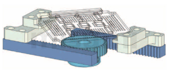
■ Linear Motion: Rack and Pinion Drive
Bracket Micro Gear Type Slide Table Assembly
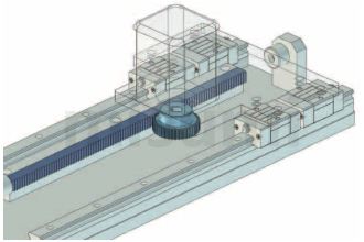
Positioning Mechanism for Basic Frame
Precautions
■ Cutting Method for Rack End Face
■ Rack Connection Method
The end face machining accuracy of MISUMI racks is less than the pitch.
Therefore, please leave a gap between the two racks as shown in the diagram below, and connect them after adjusting the pitch using a combination rack (racks with the same module).


■ Rack Connection Method
The end face machining accuracy of MISUMI racks is less than the pitch.
Therefore, please leave a gap between the two racks as shown in the diagram below, and connect them after adjusting the pitch using a combination rack (racks with the same module).

Example of Use


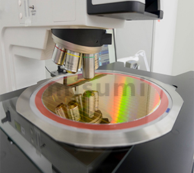
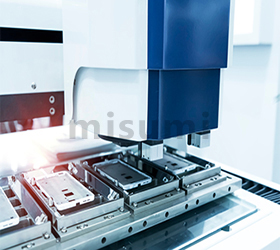
Application Industries

Related Products


Related Documents
For related information on gears, please refer to  Gear Technical Information
For information on metal materials and their surface treatment, please refer toRust Prevention and Maintenance of Metal Materials and Their Surface Treatment
Gear Technical InformationFor information on metal materials and their surface treatment, please refer to
Rust Prevention and Maintenance of Metal Materials and Their Surface TreatmentPart Number
CAD Data download and 3D preview are not available because the part number has not yet been determined.
- *In order to open the CAD Data download and 3D preview screen, the part number must be fixed.
- Please confirm the part number from "Specification / Dimension"on the left side, and then perform the CAD Data Download / 3D Preview operation.
Loading...
Basic Information
| Shape | Rack | End Machining | Both Ends Machined |
|---|
Specification/Dimensions
-
Total Length L(mm)
-
Module
-
Tooth Width W(mm)
-
Surface Treatment
- Not Provided
- Black Oxide Coating
-
Number of Effective Teeth(teeth)
-
Hole machining
- HT (Reverse Threaded Hole)
- N (No Hole Machining)
- ST (Side Threaded Hole)
- Z (Side Counterbore)
-
Style
- Designated hole position type
- Fixed hole position
-
Hole Position (1st) [ A ](mm)
-
CAD
- 2D
- 3D
Days to Ship
-
- All
- 14 Day(s) or Less
Specify Alterations
- The specifications and dimensions of some parts may not be fully covered. For exact details, refer to manufacturer catalogs .
Additional Products in this Category
- Rack Gear Round Rack - L Fixed / Configurable, Pressure Angle 20°
- Induction Hardened Rack Gears-Ground
- Circular Rack, Pressure Angle 20°, Length Fixed
- Rack Gears-L Fixed/Economy Type/Both Ends Machined Type, Economy series
- Rack Gear Round Rack - L Fixed / Configurable, Pressure Angle 20°, Economy series
- KCPF rack gear (with finishing of both ends)
- KFH Mounting Hole Machined Rack Gear (Both Ends Finished)
- S45C Rack
Tech Support
- Credit Card
- Bank Transfer
Social Media
MISUMI Contact
Copyright © MISUMI Corporation All Rights Reserved.
How can we improve?
How can we improve?
While we are not able to respond directly to comments submitted in this form, the information will be reviewed for future improvement.
Customer Privacy Policy
Thank you for your cooperation.
While we are not able to respond directly to comments submitted in this form, the information will be reviewed for future improvement.
Please use the inquiry form.
Customer Privacy Policy