(!)Due to Microsoft's end of support for Internet Explorer 11 on 15/06/2022, this site does not support the recommended environment.
- [Announcement] MISUMI Malaysia website new user interface. Clearer navigation, easy product search and more. Explore now! May contact us at (60) 3 7890 6399 for any inquiries.
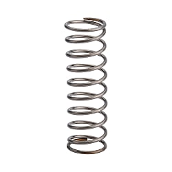
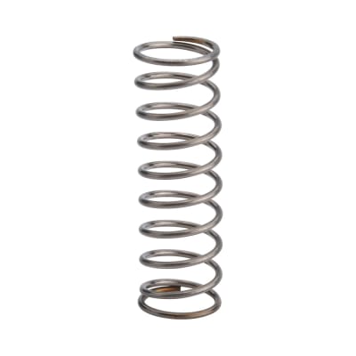
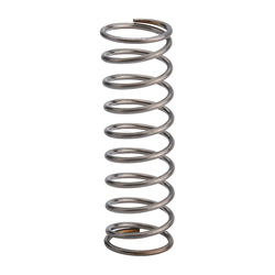
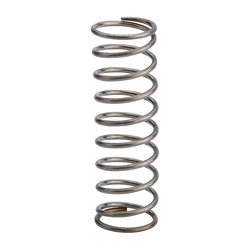
Round Wire Coil Springs, Defection O.D. Referenced, Stainless Steel, Heavy Load【1-100 Pieces Per Package】 (C-UM13-25)


- Volume Discount
[Features]·This is an outer diameter standard type spring. Note that this product is manufactured with priority given to the outer diameter tolerance. ·Although it is a stainless steel spring, it is magnetic. Please note.
- RoHS
Part Number
Configured Part Number is shown.
C-UM13-25
Economy Round Wire Coil Springs
- Superior performance with stainless steel durability.
- O.D. Referenced design ensures exact fit and reliable performance.
- Available in a variety of lengths and diameters to meet your needs.
- High quality at a lower cost, perfect for budget-conscious projects.
- Configurable spring constant and load capacity for tailored solutions.

MISUMI Standard

Cheaper Price

Product Variety

3D CAD Support
♢Stainless steel springs are also magnetic. Please be careful.

| Outer Diameter D | φ10 or Less  | Free Length L | 50 or Less | ±1mm | |
φAbove 12  | Above 60 | ±2mm | |||
| Material of Round Wire Springs | |||||
| Material SUS304-WPB Spring Constant ±10% | |||||
 The outer diameter standard type gives priority to guaranteeing the outer diameter, while the inner diameter is for reference only.
| TYPE | Coil O.D. D - Free Length L | Wire Diameter d | Solid Length | F max. | N{kgf} max. | Fa% | ||
| C-UM | 4- | 5* | 0.4 | 2.2 | 1.75 | 3.4 | {0.35} | 35 |
| 10* | 0.5 | 4.9 | 3.5 | 6.8 | {0.7 } | |||
| 15 | 0.55 | 7.5 | 5.25 | 10.3 | {1.05} | |||
| 20 | 0.6 | 11.1 | 7.0 | 13.7 | {1.4 } | |||
| 5- | 5* | 0.45 | 2.25 | 1.75 | 3.4 | {0.35 } | ||
| 10* | 0.5 | 3.13 | 3.5 | 6.8 | {0.7 } | |||
| 15 | 0.65 | 8.45 | 5.25 | 10.3 | {1.05} | |||
| 20 | 0.65 | 8.45 | 7.0 | 13.7 | {1.4 } | |||
| 30 | 0.7 | 11.9 | 10.5 | 24.0 | {2.45} | |||
| 35 | 0.75 | 16.5 | 12.25 | 20.6 | {2.1 } | |||
| 6- | 5* | 0.55 | 2.7 | 1.7 | 4.9 | {0.5 } | ||
| 10 | 0.7 | 5.6 | 3.5 | 10.8 | {1.1 } | |||
| 15 | 0.75 | 7.4 | 5.2 | 15.7 | {1.6 } | |||
| 20 | 0.75 | 7.4 | 7.0 | 20.6 | {2.1 } | |||
| 25 | 0.85 | 12.8 | 8.7 | 25.5 | {2.6 } | |||
| 30 | 0.85 | 12.8 | 10.5 | 31.4 | {3.2 } | |||
| 35 | 0.9 | 16.7 | 12.2 | 36.3 | {3.7 } | |||
| 40 | 0.9 | 16.8 | 14.0 | 41.2 | {4.2 } | |||
| 8- | 10 | 0.85 | 6.4 | 3.5 | 10.8 | {1.1 } | ||
| 15 | 0.9 | 7.9 | 5.3 | 15.7 | {1.6 } | |||
| 20 | 0.9 | 7.9 | 7.0 | 20.6 | {2.1 } | |||
| 25 | 0.9 | 7.9 | 8.8 | 25.5 | {2.6 } | |||
| 30 | 1.0 | 12.0 | 10.5 | 31.4 | {3.2 } | |||
| 35 | 1.0 | 12.0 | 12.3 | 36.3 | {3.7 } | |||
| 10- | 10 | 0.9 | 5.2 | 3.5 | 10.8 | {1.1 } | ||
| 15 | 1.0 | 7.3 | 5.3 | 15.7 | {1.6 } | |||
| 20 | 1.0 | 7.3 | 7.0 | 20.6 | {2.1 } | |||
| 25 | 1.1 | 10.5 | 8.8 | 25.5 | {2.6 } | |||
| 30 | 1.1 | 10.5 | 10.5 | 31.4 | {3.2 } | |||
| 13- | 15 | 1.2 | 8.4 | 5.3 | 15.7 | {1.6 } | ||
| 20 | 1.3 | 11.1 | 7.0 | 20.6 | {2.1 } | |||
| 25 | 1.3 | 11.1 | 8.8 | 25.5 | {2.6 } | |||
| 40 | 1.4 | 15.1 | 14.0 | 41.2 | {4.2} | |||
| 20- | 30 | 1.9 | 13.3 | 10.5 | 52.0 | {5.3 } | ||
{kgf}=N×0.101972
The outer diameter standard type gives priority to guaranteeing the outer diameter, while the inner diameter is for reference only| TYPE | Coil O.D. D - Free Length L | Wire Diameter d | Solid Length | F max. | N{kgf} max. | Fa% | ||
| C-UH | 4- | 5* | 0.45 | 2.7 | 1.5 | 4.4 | { 0.45} | 30 |
| 10* | 0.5 | 3.8 | 3.0 | 8.8 | { 0.9 } | |||
| 15 | 0.6 | 8.1 | 4.5 | 13.2 | { 1.35} | |||
| 5- | 5* | 0.55 | 3.3 | 1.5 | 4.4 | { 0.45 } | ||
| 10 | 0.6 | 4.65 | 3.0 | 8.8 | { 0.9 } | |||
| 15 | 0.6 | 4.65 | 4.5 | 13.2 | { 1.35} | |||
| 25 | 0.75 | 11.81 | 7.5 | 22.1 | { 2.25} | |||
| 6- | 5* | 0.65 | 3.2 | 1.5 | 8.8 | { 0.9 } | ||
| 10 | 0.7 | 3.9 | 3.0 | 17.7 | { 1.8 } | |||
| 15 | 0.85 | 7.7 | 4.5 | 26.5 | { 2.7 } | |||
| 20 | 0.9 | 9.7 | 6.0 | 35.3 | { 3.6 } | |||
| 25 | 1.0 | 15.5 | 7.5 | 44.1 | { 4.5 } | |||
| 30 | 1.0 | 15.5 | 9.0 | 53.0 | { 5.41 } | |||
| 8- | 10 | 0.9 | 5.3 | 3.0 | 17.7 | { 1.8 } | ||
| 15 | 0.9 | 5.3 | 4.5 | 26.5 | { 2.7 } | |||
| 20 | 1.1 | 11 | 6.0 | 35.3 | { 3.6 } | |||
| 25 | 1.1 | 11 | 7.5 | 44.1 | { 4.5 } | |||
| 30 | 1.2 | 15.9 | 9.0 | 53.0 | { 5.4 } | |||
| 10- | 15 | 1.1 | 6.9 | 4.5 | 26.5 | { 2.7 } | ||
| 20 | 1.2 | 9.3 | 6.0 | 35.3 | { 3.6 } | |||
| 25 | 1.2 | 9.3 | 7.5 | 44.1 | { 4.5 } | |||
| 30 | 1.3 | 12.7 | 9.0 | 53.0 | { 5.4 } | |||
| 35 | 1.4 | 17.5 | 10.5 | 61.8 | { 6.3 } | |||
| 13- | 15 | 1.5 | 9.2 | 4.5 | 44.1 | { 4.5 } | ||
| 20 | 1.5 | 9.2 | 6.0 | 58.8 | { 6 } | |||
| 25 | 1.5 | 9.2 | 7.5 | 73.5 | { 7.5 } | |||
| 30 | 1.8 | 18 | 9.0 | 88.3 | { 9 } | |||
| 50 | 2.0 | 28.5 | 15.0 | 147.0 | {15.0 } | |||
| 16- | 45 | 2.2 | 25.1 | 13.5 | 132.4 | { 13.51 } | ||
| 20- | 30 | 2.3 | 13.8 | 9.0 | 132.4 | { 13.51 } | ||
| 35 | 2.5 | 18.8 | 10.5 | 154.9 | { 15.81 } | |||
| 40 | 2.5 | 18.8 | 12.0 | 176.5 | { 18.01 } | |||
| 45 | 2.8 | 29.4 | 13.5 | 199.1 | { 20.32 } | |||
Both ends of C-UM/C-UH models with * are not ground.● Calculation method of laps (reference value):
Total number of laps = solid length ÷ wire diameter (d)-1
Effective laps=total number of laps-2
*The number of laps is a reference value. There will be some deviations among batches.
The solid length is a reference value. There will be slight differences among batches.Moreover, if it is used under the limit condition of the solid length, it may cause the spring to be deformed or be damaged after using only a limited number of times.
Be sure to use within the allowable displacement Fmax.(mm)■Spring Constant The spring constant
D12 is for C-UY・C-UR・C-UF・C-UBB only. D14 is for C-UBB only.| Type | C-UV | C-UY | C-UR | C-UF | C-UL | C-UTT | C-UM | C-UH | C-UBB | |||||||||||||||||||
| D | ||||||||||||||||||||||||||||
| 2 | 0.05{0.005} | 0.2{0.02} | 0.3{0.03} | 0.5{0.05} | ||||||||||||||||||||||||
| 3 | N/mm 0.05 {kgf/mm}{0.005} | N/mm 0.098 {kgf/mm}{0.01} | N/mm 0.29 {kgf/mm} {0.03} | N/mm 0.49 {kgf/mm} {0.05} | N/mm 0.98 {kgf/mm} {0.1} | 1.5{0.15} | ||||||||||||||||||||||
| 4 | 2.0 {0.2} | 2.9{0.3} | 4.9{0.5} | |||||||||||||||||||||||||
| 5 | N/mm 2.0 {kgf/mm} {0.2} | |||||||||||||||||||||||||||
| 6 | N/mm 2.9 {kgf/mm} {0.3} | N/mm 5.9 {kgf/mm} {0.6} | N/mm 9.8 {kgf/mm} {1.0} | |||||||||||||||||||||||||
| 8 | ||||||||||||||||||||||||||||
| 10 | N/mm 0.2 {kgf/mm} {0.02} | |||||||||||||||||||||||||||
| 12 | ||||||||||||||||||||||||||||
| 13 | N/mm 9.8 {kgf/mm} {1.0} | N/mm 19.6 {kgf/mm} {2.0} | ||||||||||||||||||||||||||
| 14 | ||||||||||||||||||||||||||||
| 16 | ||||||||||||||||||||||||||||
| 20 | 0.3{0.03} | 0.5{0.05} | 0.98{0.1} | 2.9{0.3} | 3.9{0.4} | 4.9{0.5} | 14.7{1.5} | 29.4{3.0} | ||||||||||||||||||||
| Fmax. | F=L×70% | F=L×75% | F=L×60% | F=L×45% | F=L×40% | F=L×40% | F=L×35% | F=L×30% | F=L×25% | |||||||||||||||||||
Select an appropriate Round Wire Springs type according to the actual installation situation, and refer to the published content for the specific inner and outer diameter tolerance values.
* The solid length is a reference value. If it is used under the limit condition of the solid length, the spring may be deformed, or damaged after using only a limited number of times. Therefore, use within the allowable displacement Fmax.(mm).
To increase the usage count, it is recommended to use the spring up to 70% of the allowable displacement Fmax..
 *The test data are obtained through testing by our company, which are for reference only. *Generic products on the market are similar products randomly purchased by our company from online or offline markets | 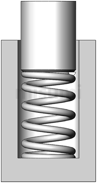 Installation Diagram of Outer Diameter Standard Type Round Wire Coil Spring |
Operating temperature of Round Wire Springs
SWP-A……Normal temperature (0~40℃)
Stainless steel……-10~100℃
Spring oil tempered steel wire……Normal temperature (0~40℃)
*If the spring is used under conditions exceeding the above temperature, the load value may decrease due to usage conditions.
*When used in an environment with high and low temperature differences and humidity such as outdoors, it is recommended to choose stainless steel products.
* Heat-resistant springs can also be used. For details, refer to the Plastic Mold Components Catalog.
Stainless steel springs are also magnetic. Please be careful.

A Round Wire Springs is mechanism for positioning the workpiece based on the hole reference.
Loosening during positioning can be reduced by using a tapered pin to eliminate the deviation caused by the tolerance of each workpiece hole.
Select the compression spring to move from the beginning of the positioning contact with the workpiece.
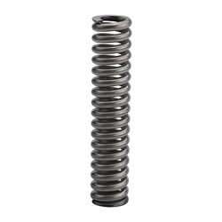 |  |  |
| (Economy series) Round Wire Springs - Outer Diameter Standard Stainless Steel, Ultra Heavy Load, Spring Constant 4.9 to 29.4N/mm | (Economy series) Round Wire Springs - Inner Diameter Standard Stainless Steel, Light Load, Spring Constant 0.29 to 0.49 N/mm | (Economy series) Round Wire Springs - Outer Diameter Standard Stainless Steel, Light Load, Spring Constant 0.5 to 3.9 N/mm |
| Reason for Recommendation: MISUMI Basic Round Wire Springs, Outer Diameter Standard Type, Ultra Heavy Load Type | Reason for Recommendation: MISUMI Basic Round Wire Springs, Inner Diameter Standard Type, Light Load Type | Reason for Recommendation: MISUMI Basic Round Wire Springs, Outer Diameter Standard Type, Light Load Type |
Part Number
CAD Data download and 3D preview are not available because the part number has not yet been determined.
- *In order to open the CAD Data download and 3D preview screen, the part number must be fixed.
- Please confirm the part number from "Specification / Dimension"on the left side, and then perform the CAD Data Download / 3D Preview operation.
| Part Number |
|---|
| C-UM13-25 |
| Part Number | Standard Unit Price | Minimum order quantity | Volume Discount | Days to Ship | Free Length L (mm) | Inner Dia. D-2d (or D) (Ø) | Outer Dia. D (or D1) (Ø) | Spring Constant (N/mm) | Material | Wire Dia. (Ø) | Height H2 at Allowable Load (mm) | Allowable Load P2 (N) | End Face Condition | Total Number of Turns N | Solid Length (mm) | Allowable Displacement (mm) | Sales Package |
|---|---|---|---|---|---|---|---|---|---|---|---|---|---|---|---|---|---|
MYR 1.91 | 1 Piece(s) | Available | 1 Day(s) | 25 | 10.4 | 13 | 2.9 | SUS304-WPB | 1.3 | 16.3 | 25.5 | Grinding | 7.5 | 11.1 | 8.7 | Single Item |
Loading...
Please check the type/dimensions/specifications of the part C-UM13-25 in the Round Wire Coil Springs, Defection O.D. Referenced, Stainless Steel, Heavy Load series.
Specification/Dimensions
-
type
- C-UH
- C-UM
-
Free Length L(mm)
-
Inner Dia. D-2d (or D)(Ø)
-
Outer Dia. D (or D1)(Ø)
-
Spring Constant(N/mm)
-
Material
- SUS304-WPB
-
Wire Dia.(Ø)
-
Sales Package
- Single Item
-
CAD
- 2D
- 3D
Days to Ship
-
- All
- 1 Day(s) or Less
- 6 Day(s) or Less
- 9 Day(s) or Less
- 10 Day(s) or Less
- 11 Day(s) or Less
- 13 Day(s) or Less
Specify Alterations
- The specifications and dimensions of some parts may not be fully covered. For exact details, refer to manufacturer catalogs .
Frequently asked question (FAQ)
- Question: How long is the life of a basic round wire coil spring?
-
Answer:
Unfortunately, there are no specific test values as reference regarding the life of a round wire coil spring because there is individual difference to a certain extent and the installation conditions are complicated.
The usage count varies with the operating temperature, environment, and amount of deformation. To increase the usage count, it is recommended to use the spring up to 70% of the allowable displacement Fmax.. - Question: What are the JIS standards for general spring-related materials?
-
Answer:
Piano wires: JIS G 3522
Iron wires: JIS G 3532
Hard drawn steel wires: JIS G 3521
Stainless steel wires for springs: JIS G 4313 - Question: What influence will the usage without a spring rail have on the spring?
-
Answer:
The usage without a spring rail will cause buckling of the spring, bending of its body and other problems, leading to breakage due to high stress locally generated on the inner side of the bending part. To ensure the service life of the spring, install the spring using the shaft, outer diameter guide rail, etc.
*Basically, it is ideal to use the intermediate shaft of the inner diameter side guide rail by passing it through from the upper surface to the lower surface. - Question: What influence will the usage count of more than 300,000 times beyond the maximum displacement (when used close to the solid length) have on the spring?
- Answer: The usage count of more than 300,000 times beyond the maximum displacement (when used close to the solid length) will cause high stress breakage above the calculated value on the section. In addition, near the solid length, the effective coil part will gradually get close and the spring constant will increase. Therefore, be sure to use within the allowable displacement Fmax.(mm).
- Question: What is the difference between a piano steel wire spring and a hard drawn steel wire spring?
-
Answer:
There is little difference in appearance between the two materials. In short, the piano wire is an advanced material, and the hard drawn steel wire is a general material.
The piano wire is often used as a spring for precision machinery while the hard drawn steel wire is mostly used as a peripheral spring for groceries or blinds.
They are both high-carbon steels with almost the same chemical composition. The production of piano wires is time-consuming and they are expensive because there is additional standardized management and inspection of impurities, the depth of surface scars, and the depth of decarburized layer.
Although the subtle difference is invisible to the naked eye, it has a great influence on the quality of the spring.
Products like this...
| Part Number |
|---|
| C-UH10-20-PACK |
| C-UH10-25 |
| C-UH10-25-PACK |
| C-UM13-25-PACK |
| C-UM13-30-PACK |
| C-UM13-40 |
| Part Number | Standard Unit Price | Number of pc(s). included in pkg. | Minimum order quantity | Volume Discount | Days to Ship | Free Length L (mm) | Inner Dia. D-2d (or D) (Ø) | Outer Dia. D (or D1) (Ø) | Spring Constant (N/mm) | Material | Wire Dia. (Ø) | Height H2 at Allowable Load (mm) | Allowable Load P2 (N) | End Face Condition | Total Number of Turns N | Solid Length (mm) | Allowable Displacement (mm) | Sales Package |
|---|---|---|---|---|---|---|---|---|---|---|---|---|---|---|---|---|---|---|
MYR 140.76 | 100 Pieces Per Package | 1 Pack(s) | Available | 6 Day(s) | 20 | - | 10 | - | - | - | - | - | - | - | - | - | - | |
MYR 1.58 | 1 Piece(s) | Available | 1 Day(s) | 25 | 7.6 | 10 | 5.9 | SUS304-WPB | 1.2 | 17.5 | 44.1 | Grinding | 6.8 | 9.3 | 7.5 | Single Item | ||
MYR 135.25 | 100 Pieces Per Package | 1 Pack(s) | Available | 6 Day(s) | 25 | - | 10 | - | - | - | - | - | - | - | - | - | - | |
MYR 176.41 | 100 Pieces Per Package | 1 Pack(s) | Available | 6 Day(s) | 25 | - | 13 | - | - | - | - | - | - | - | - | - | - | |
MYR 183.12 | 100 Pieces Per Package | 1 Pack(s) | Available | 13 Day(s) | 30 | 10.2 | 13 | 2.9 | SUS304-WPB | 1.4 | 19.5 | 31.4 | Grinding Processing | 9.8 | 15.1 | 10.5 | - | |
MYR 2.54 | 100 Piece(s) | Available | 10 Day(s) | 40 | 10.2 | 13 | 2.9 | SUS304-WPB | 1.4 | 26 | 41.2 | Grinding Processing | 9.7 | 15.1 | 14 | - |
Additional Products in this Category
- Round Wire Coil Springs/Deflection 15%-25%/O.D. Referenced
- Compression Spring (1m) EA952S-144
- Compression Spring (1m) EA952S-151
- Compression Spring (1m) EA952S-221
- Compression Spring (1m) EA952S-302
- Compression Spring (Stainless Steel) EA952SF-78
- Compression Spring (Stainless Steel) EA952SF-97
- [Stainless Steel] Compression Spring EA952VQ-34
Tech Support
- Credit Card
- Bank Transfer
Social Media
MISUMI Contact
Copyright © MISUMI Corporation All Rights Reserved.
How can we improve?
How can we improve?
While we are not able to respond directly to comments submitted in this form, the information will be reviewed for future improvement.
Customer Privacy Policy
Thank you for your cooperation.
While we are not able to respond directly to comments submitted in this form, the information will be reviewed for future improvement.
Please use the inquiry form.
Customer Privacy Policy