(!)Due to Microsoft's end of support for Internet Explorer 11 on 15/06/2022, this site does not support the recommended environment.
- [Announcement] MISUMI Malaysia website new user interface. Clearer navigation, easy product search and more. Explore now! May contact us at (60) 3 7890 6399 for any inquiries.
Antistatic PVC Plates -Chemical Resistant & Flame Retardant (Part Numbers)
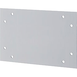


Excels in chemical resistance and flame retardance, and superior in cost-effectiveness among anti-static materials.
(i)Caution
- Due to a change of materials manufacturer, the protective film used in TYPE: ENBBT will change as soon as current stock runs out (expected to be in early October 2024). There will be no changes to physical properties or colors due to this change of manufacturer.
Part Number
Configured Part Number is shown.
Drawing
 1 to 16 × Bolt Nominal Dia. Selection
[!] The pitch between holes is equally divided. The formula for calculating the pitch is ap = (A - 2C) / (a - 1),
bp = (B - 2D)/(b - 1).
[!] When the number of holes per side is 1, the (C) and (D) dimensions are not applied to the holes from the end face. (Asymmetrical machining)
[ ! ] Only burrs generated on the cut part are removed.
To prevent cuts on the corners, please specify additional machining for 4 corners of the same size.
| Hole Machining Details | ||||||||||||||||||||||||||||||
| N (Through Hole) | P (Countersink) | Hole Machining Conditions (N・P) | ||||||||||||||||||||||||||||
 |  |  | ||||||||||||||||||||||||||||
|
| |||||||||||||||||||||||||||||
| Q (Keyhole) | Hole Machining Condition Q (Keyhole) | |||||||||||||||||||||||||||||
 |
| [ ! ] Keyhole Machining Condition c ≥ 5 | ||||||||||||||||||||||||||||
[ ! ] | "Keyhole Position" (1): The hole position for the specified dimensions D and bp is at the center of d1 . (2): When there are 3 or more holes on one side, the pitch is equally divided around d1. (3): The center of diameter d1 for the keyhole is consistent with the value for the center of C(D). | |||||||||||||||||||||||||||||

 ■Number of Holes Combination Table ■Part Number Ordering Codes
 [!] The formula for calculating the total number of holes is 2a + 2b - 4. When a and b are 1, then a × b.
| Machining Method | Surface texture | |
| 4 Sides | Circular sawing |  |
| Upper-Lower Surface | Material |  |
■ Accuracy Standards
● T Dimension Tolerance: ±0.5
● Dimension tolerance of A and B: ±1.0
[ ! ] For A and B dimensions, please specify A≧B.
 4 to 16 × Bolt Nominal Dia. Selection
[!] The pitch between holes is equally divided. The formula for calculating the pitch is ap = (A - 2C)/ (a - 1),
bp = (B - 2S)/(b - 1).
[ ! ] Only burrs generated on the cut part are removed.
To prevent cuts on the corners, please specify additional machining for 4 corners of the same size.
| Hole Machining Details | ||||||||||||||||||||||||||||||
| N (Through Hole) | P (Countersink) | Hole Machining Conditions (N・P) | ||||||||||||||||||||||||||||
| | | ||||||||||||||||||||||||||||
|
| |||||||||||||||||||||||||||||
| Q (Keyhole) | Hole Machining Condition Q (Keyhole) | |||||||||||||||||||||||||||||
|
| [ ! ] Keyhole Machining Condition c ≥ 5 | ||||||||||||||||||||||||||||
[ ! ] | "Keyhole Position" (1): The hole position for the specified dimensions D/R and bp is at the center of d1. (2): When there are 3 or more holes on one side, the pitch is equally divided around d1. (3): The center of the diameter d1 for the keyhole is consistent with the value for the center of D(R). | |||||||||||||||||||||||||||||
 ■Number of Holes Combination Table ■Part Number Ordering Codes
 [ ! ] The formula for calculating the total number of holes is 2a + 2b.
| Machining Method | Surface texture | |
| 4 Sides | Circular sawing | |
| Upper-Lower Surface | Material | |
■ Accuracy Standards
● T Dimension Tolerance: ±0.5
● Dimension tolerance of A and B: ±1.0
[ ! ] For A and B dimensions, please specify A≧B.
 2 holes 2H4 holes 4H6 holes 6H8 holes 8H8 holes 8HV [ ! ] Light transmission: ENBT80%, ENBBT29%
| "Keyhole Position" 1: For 2H, the center of diameter d1 is consistent with G. 2: For 4H and 6H, the center of G dimension is consistent with the center of B dimension. 3: For 8H, the center of diameter d1 of the middle keyhole is consistent with the center of B dimension. |
| ||||||||||||||||||||||||||||||||||||||||||||||||||||||
 | [ ! ] Keyhole Machining Conditions a ≥ 5 b ≥ 5 | |||||||||||||||||||||||||||||||||||||||||||||||||||||||

■ Accuracy Standards
● T Dimension Tolerance: ±0.5
● Dimension Tolerance of A and B: ±1.0

[ ! ]A ≥ B
■ Accuracy Standards
● T Dimension Tolerance: ±0.5
● Dimension Tolerance of A and B: ±1.0
Product Specifications
| Type | [ M ] Grade | Color | Light Transmittance | Operating Ambient Temperature |
| ENBT | Antistatic | Transparent | 80% | -30 to 60°C |
| ENBBT | Antistatic | Smoke Brown | 29% |
| Item | Testing Method JIS | Unit | PVC (PVC) | |||
| Standard | Antistatic | |||||
| Mechanical Properties | Tensile Strength | K-7113 | Mpa {kgf/cm2} | 71 0 to 20 | 63 {640} | |
| Elongation | K-7113 | % | — | 50 | ||
| Bending Strength | K-7203 | Mpa {kgf/cm2} | — — | 98 {1000} | ||
| Flexural Modulus | K-7203 | Mpa | — | 3.4 × 10³ | ||
| Compression Strength | Yield Point | K-7181 | Mpa {kgf/cm2} | — — | 83 {850} | |
| Izod Impact Strength | K-7110 | kJ/m2 | — | 2.9 | ||
| Rockwell Hardness | M Scale | — | — | — | — | |
| Thermal Characteristics | Continuous Use | — | °C | -30 to 60 | -30 to 60 | |
| Deflection Temp. Under Load | 0.45 MPa | K-7191 | °C | 61 | — | |
| Linear Expansion Coefficient | K-7140 | °C-1 | — | 7.0 × 10⁻⁵ | ||
| Thermal Conductivity | — | W/m·K | 0.17 | 0.16 | ||
| Specific Heat | — | J/g·K | — | 1.12 | ||
| Electric Characteristics | Surface Resistivity | K-6911 | Ω | > 1015 | 107Up to 108 | |
| Specific Volume Resistivity | K-6911 | Ω·cm | > 1015 | — | ||
| Insulation Breakdown Voltage | K-6911 | kV/mm | > 26 | — | ||
| Dielectric Constant | 106 Hz | K-6911 | — | 3.0 | — | |
| Dissipation Factor | 106 Hz | K-6911 | — | 0.02 | — | |
| Transmittance | Light transmittance by color | Transparent | — | % | 88 | 80 |
| Smoke Brown | 21 | 29 | ||||
| Orange | — | — | ||||
| Smoke Gray | — | — | ||||
| Visible Light Transmittance | - | % | — | — | ||
| Others | Specific Gravity | — | — | 1.4 | 1.4 | |
| Water Absorption Ratio | K-7209 | % | 0.0 | 0.03 | ||
| Flame Resistance | — | — | V-0 equivalent | V-0 equivalent | ||
| Chemical Resistance | Oil | — | — | ○ | ○ | |
| Acid | — | — | ○ | ○ | ||
| Alkali | — | — | ○ | ○ | ||
| Organic Solvent | — | — | △ | × ~△ | ||
Specification Table
| Part Number | — | A | — | B | — | T | — | C | — | D | — | Screw Nominal Dia. |
| ENBT33W8 | — | 200 | — | 100 | — | 5 | — | C20 | — | D10 | — | N5 |
| Part Number | — | A | — | B | — | T | — | C | — | D | — | R | — | S | — | Screw Nominal Dia. |
| ENBT22V8 | — | 200 | — | 100 | — | 5 | — | C60 | — | D20 | — | R20 | — | S60 | — | N5 |
| Part Number | — | A | — | B | — | T | — | F | — | G | — | Screw Nominal Dia. |
| ENBBT6H | — | 800 | — | 400 | — | 3 | — | F375 | — | G350 | — | N5 |
| Part Number | — | A | — | B | — | T |
| ENBT | — | 955 | — | 825 | — | 5 |
| Part Number | A | B | T | Hole position indication | Bolt Nominal Dia. Selection | |||||||||||
| TYPE | combination of holes | 1 mm Increments | Selection | C | D | Through Hole | Countersunk Hole | Keyhole | ||||||||
| Side A Number of Holes | Side B Number of Holes | Hole Machining Shape | Number of Holes | 1 mm Increments | N | P | Q | |||||||||
| ENBT ENBBT | 1 2 3 4 5 | 1 2 3 4 5 | W | 1 3 5 8 12 16 | 2 4 6 10 14 | 100 ~ 1100 | 100 ~ 900 | 3 | 9 ~ 1091 | 9 ~ 891 | 3 4 5 6 8 | 3 | 5 6 8 | |||
| 5 | 3 | 4 | 5 | 6 | ||||||||||||
When drilling through holes or countersunk holes, a distance of 2.5 mm or more is required between the holes or between the end faces and holes. A distance of 5 mm or more is required for keyholes.
| Part Number | A | B | T | Hole position indication | Bolt Nominal Dia. Selection | ||||||||||||
| TYPE | combination of holes | 1 mm Increments | Selection | C | D | R | S | Through Hole | Countersunk Hole | Keyhole | |||||||
| Side A Number of Holes | Side B Number of Holes | Hole Machining Shape | Number of Holes | 1 mm Increments | N | P | Q | ||||||||||
| ENBT ENBBT | 1 2 3 4 | 1 2 3 4 | V | 4 6 8 10 12 14 16 | 100 ~ 1100 | 100 ~ 900 | 3 | 9 ~ 1091 | 9 ~ 891 | 9 ~ 1091 | 9 ~ 891 | 3 4 5 6 8 | 3 | 5 6 8 | |||
| 5 | 3 | 4 | 5 | 6 | |||||||||||||
When drilling through holes or countersunk holes, a distance of 2.5 mm or more is required between the holes or between the end faces and holes. A distance of 5 mm or more is required for keyholes.
[ ! ] If the number of holes on the A side or on the B side is 3 or more, specify the dimensions as C ≥ R and S ≥ D.
| Part Number | 1 mm Increments | Selection T | 1 mm Increments | Bolt Nominal Dia. Selection | ||||||||||
| Type | Number of Holes | A | B | F | G | X | Y | N (Through Hole) | P (Countersink) | Q (Keyhole) | ||||
| ENBT ENBBT | 2H 4H 6H 8H | 100 〜 1100 | 100 〜 900 | 3 | 9 to 1091 (2H, 4H type) 9 to 545 (6H/8H/8HV Type) | 5 to 895 (2H Type) 9 to 891 (4H/6H Type) 9 to 445 (8H/8HV Type) | — | — | 3 4 5 6 8 | 3 | 5 6 8 | |||
| 5 | 3 | 4 | 5 | 6 | ||||||||||
| 8HV | 3·5 | 19 to 535 | 19 to 435 | — | — | |||||||||
[!] Dimension F specification range - 2H/4H type selection: d (d1)/2 + 2.5 ≤ G ≤ B - d (d1)/2 - 2.5; 4H/6H type selection: d (d1) + 5 ≤ G ≤ B - d (d1) - 5; 8H type selection: d (d1) +5 ≤ G ≤ B/2 − d (d1) /2 − 2.5, 8HV type selection: Y + 2d + 10 < G ≤ B - d - 5 is required. (d for through hole, d1 for countersink)
[!] Dimension X specification range – 2H/4H/6H/8H type selection: d + 5 ≤ X ≤ A / 2 - d / 2 - 2.5; 8HV type selection: F + 2d + 10 < X ≤ A - d - 5 is required.
[!] Dimension Y specification range – 2H/4H/6H/8H type selection: d + 5 ≤ Y ≤ B / 2 - d / 2 - 2.5; 8HV type selection: d + 5 ≤ Y < G - 2D - 10 is required.
| Part Number | 1 mm Increments | Selection T | |
| Type | A | B | |
| ENBT ENBBT | 100 to 1100 | 100 to 900 | 3 5 |
Alterations
| Part Number | — | A | — | B | — | T | — | C | — | D | — | Screw Nominal Dia. | — | (ACC,ACR) |
| ENBT33W8 | — | 200 | — | 100 | — | 5 | — | C20 | — | D10 | — | N5 | — | ACC |
| Alterations | Same Dimension Machining (5 mm) for 4 Corners | |||||||
 |  | |||||||
| Code | ACC | ACR | ||||||
| Spec. | All four corners can be cut and radius machined to the same dimensions (5 mm). ·ACC: Corner 5 mm Cut ·ACR: Corner 5 mm Radius Machining [ ! ] For the machining conditions of the hole and plate end face, see 
| |||||||
| Part Number | — | A | — | B | — | T | — | C | — | D | — | R | — | S | — | Screw Nominal Dia. | — | (ACC,ACR) |
| ENBT22V8 | — | 200 | — | 100 | — | 5 | — | C60 | — | D20 | — | R20 | — | S60 | — | N5 | — | ACR |
| Alterations | Same Dimension Machining (5 mm) for 4 Corners | |||||||
| | |||||||
| Code | ACC | ACR | ||||||
| Spec. | All four corners can be cut and radius machined to the same dimensions (5 mm). ·ACC: Corner 5 mm Cut ·ACR: Corner 5 mm Radius Machining [ ! ] For the machining conditions of the hole and plate end face, see
| |||||||
| Part Number | — | A | — | B | — | T | — | F | — | G | — | Screw Nominal Dia. | — | (XC·YC·CN, etc.) |
| ENBT4H | — | 500 | — | 400 | — | 3 | — | F300 | — | G300 | — | N6 | — | XC15·YC35 |
| Alterations | Hole Position from Left | Hole Position from Bottom | Same Dimension Machining (5 mm) for 4 Corners | |||||||
 |  | | | |||||||
| Code | XC | YC | ACC | ACR | ||||||
| Spec. | XC = 0.5 mm Increments [ ! ] For the machining conditions of the hole and plate end face, see Hole Machining Conditions under [ ! ] Can be specified only for hole machined type (2H to 8H) | YC = 0.5 mm Increments [ ! ] For the machining conditions of the hole and plate end face, see Hole Machining Conditions under [ ! ] Can be specified only for hole machined type (2H to 8H) | All four corners can be cut and radius machined to the same dimensions (5 mm). ·ACC: Corner 5 mm Cut ·ACR: Corner 5 mm Radius Machining [ ! ] For the machining conditions of the hole and plate end face, see
| |||||||
| Part Number | — | A | — | B | — | T | — | F | — | G | — | Screw Nominal Dia. | — | (XC·YC·CN, etc.) |
| ENBT4H | — | 500 | — | 400 | — | 3 | — | F300 | — | G300 | — | N6 | — | XC15·YC35 |
| Alterations | Aluminum Extrusion Blind Joint Notch | Relief at 4 Corners | Corner Cut | Corner Radius Machining |
 |  |  |  | |
| Code | F□□, E□□, J□□, K□□ | CN | CCA·CCB·CCC·CCD | CRA·CRB·CRC·CRD |
| Spec. | Machines relief for blind joints of aluminum extrusions. [ ! ] Can only be specified for the standard sizes of standard types | Machines relief at 4 corners. CN = 1 mm Increments [ ! ]5 ≤ CN ≤ 50 Ordering code CN = 25 >> N25 [ ! ] Can only be specified for the standard sizes of standard types | Any corner can be cut. 5 ≤ corner cut ≤ 50 10 ≤ A − C (2C) or B − C (2C) 5 mm Increments Ordering code example: when the corners of A and D are cut by C5 >> CCA5 - CCD5 [NG] Not applicable to Hole Machined Type. | Adds radius machining to any corner. R = 5 mm Increments [ ! ]10 ≤ A (B) −R (2R) [ ! ]5 ≤ CRA·CRB·CRC·CRD ≤ 100 Ordering code (Example) Adds R10 at the corner of A and C CRA10−CRC10 [NG] Not applicable to Hole Machined Type. |
Part Number
CAD Data download and 3D preview are not available because the part number has not yet been determined.
- *In order to open the CAD Data download and 3D preview screen, the part number must be fixed.
- Please confirm the part number from "Specification / Dimension"on the left side, and then perform the CAD Data Download / 3D Preview operation.
| Part Number |
|---|
| ENBBT2H-[100-1100/1]-[100-900/1]-[3,5]-F[9-1091/1]-G[5-895/1]-N[3,4,5,6,8] |
| ENBBT2H-[100-1100/1]-[100-900/1]-[3,5]-F[9-1091/1]-G[5-895/1]-P[3,4,5,6,8] |
| ENBBT2H-[100-1100/1]-[100-900/1]-[3,5]-F[9-1091/1]-G[5-895/1]-Q[5,6,8] |
| ENBBT4H-[100-1100/1]-[100-900/1]-[3,5]-F[9-1091/1]-G[9-891/1]-N[3,4,5,6,8] |
| ENBBT4H-[100-1100/1]-[100-900/1]-[3,5]-F[9-1091/1]-G[9-891/1]-P[3,4,5,6,8] |
| ENBBT4H-[100-1100/1]-[100-900/1]-[3,5]-F[9-1091/1]-G[9-891/1]-Q[5,6,8] |
| ENBBT6H-[100-1100/1]-[100-900/1]-[3,5]-F[9-545/1]-G[9-891/1]-N[3,4,5,6,8] |
| ENBBT6H-[100-1100/1]-[100-900/1]-[3,5]-F[9-545/1]-G[9-891/1]-P[3,4,5,6,8] |
| ENBBT6H-[100-1100/1]-[100-900/1]-[3,5]-F[9-545/1]-G[9-891/1]-Q[5,6,8] |
| ENBBT8H-[100-1100/1]-[100-900/1]-[3,5]-F[9-545/1]-G[9-445/1]-N[3,4,5,6,8] |
| ENBBT8H-[100-1100/1]-[100-900/1]-[3,5]-F[9-545/1]-G[9-445/1]-P[3,4,5,6,8] |
| ENBBT8H-[100-1100/1]-[100-900/1]-[3,5]-F[9-545/1]-G[9-445/1]-Q[5,6,8] |
| ENBBT8HV-[100-1100/1]-[100-900/1]-[3,5]-F[9-545/1]-G[9-545/1]-X[9-545/1]-Y[9-435/1]-N[3,4,5,6,8] |
| ENBBT8HV-[100-1100/1]-[100-900/1]-[3,5]-F[9-545/1]-G[9-545/1]-X[9-545/1]-Y[9-435/1]-P[3,4,5,6] |
| ENBBT-[100-1100/1]-[100-900/1]-[3,5] |
| ENBT2H-[100-1100/1]-[100-900/1]-[3,5]-F[9-1091/1]-G[5-895/1]-N[3,4,5,6,8] |
| ENBT2H-[100-1100/1]-[100-900/1]-[3,5]-F[9-1091/1]-G[5-895/1]-P[3,4,5,6,8] |
| ENBT2H-[100-1100/1]-[100-900/1]-[3,5]-F[9-1091/1]-G[5-895/1]-Q[5,6,8] |
| ENBT4H-[100-1100/1]-[100-900/1]-[3,5]-F[9-1091/1]-G[9-891/1]-N[3,4,5,6,8] |
| ENBT4H-[100-1100/1]-[100-900/1]-[3,5]-F[9-1091/1]-G[9-891/1]-P[3,4,5,6,8] |
| ENBT4H-[100-1100/1]-[100-900/1]-[3,5]-F[9-1091/1]-G[9-891/1]-Q[5,6,8] |
| ENBT6H-[100-1100/1]-[100-900/1]-[3,5]-F[9-545/1]-G[9-891/1]-N[3,4,5,6,8] |
| ENBT6H-[100-1100/1]-[100-900/1]-[3,5]-F[9-545/1]-G[9-891/1]-P[3,4,5,6,8] |
| ENBT6H-[100-1100/1]-[100-900/1]-[3,5]-F[9-545/1]-G[9-891/1]-Q[5,6,8] |
| ENBT8H-[100-1100/1]-[100-900/1]-[3,5]-F[9-545/1]-G[9-445/1]-N[3,4,5,6,8] |
| ENBT8H-[100-1100/1]-[100-900/1]-[3,5]-F[9-545/1]-G[9-445/1]-P[3,4,5,6,8] |
| ENBT8H-[100-1100/1]-[100-900/1]-[3,5]-F[9-545/1]-G[9-445/1]-Q[5,6,8] |
| ENBT8HV-[100-1100/1]-[100-900/1]-[3,5]-F[9-545/1]-G[9-545/1]-X[19-535/1]-Y[19-435/1]-N[3,4,5,6,8] |
| ENBT8HV-[100-1100/1]-[100-900/1]-[3,5]-F[9-545/1]-G[9-545/1]-X[19-535/1]-Y[19-435/1]-P[3,4,5,6] |
| ENBT-[100-1100/1]-[100-900/1]-[3,5] |
| Part Number | Standard Unit Price | Minimum order quantity | Volume Discount | Days to Ship | RoHS | Color | Hole Machining | Shape | A (mm) | B (mm) | Countersink Hole Nominal Dia. [P] | F (mm) | G (mm) | Keyhole Nominal Dia. [Q] | T (mm) | Through Hole Nominal Dia. [N] | X (mm) | Y (mm) |
|---|---|---|---|---|---|---|---|---|---|---|---|---|---|---|---|---|---|---|
- | 1 Piece(s) | 8 Day(s) or more | 10 | Smoke Brown | 2H | Number of Holes Selection Type (With 2H to 8H Holes) | 100 ~ 1100 | 100 ~ 900 | - | 9 ~ 1091 | 5 ~ 895 | - | 3 ~ 5 | 3 ~ 8 | - | - | ||
- | 1 Piece(s) | 8 Day(s) or more | 10 | Smoke Brown | 2H | Number of Holes Selection Type (With 2H to 8H Holes) | 100 ~ 1100 | 100 ~ 900 | 3 ~ 8 | 9 ~ 1091 | 5 ~ 895 | - | 3 ~ 5 | - | - | - | ||
- | 1 Piece(s) | 8 Day(s) or more | 10 | Smoke Brown | 2H | Number of Holes Selection Type (With 2H to 8H Holes) | 100 ~ 1100 | 100 ~ 900 | - | 9 ~ 1091 | 5 ~ 895 | 5 ~ 8 | 3 ~ 5 | - | - | - | ||
- | 1 Piece(s) | 8 Day(s) or more | 10 | Smoke Brown | 4H | Number of Holes Selection Type (With 2H to 8H Holes) | 100 ~ 1100 | 100 ~ 900 | - | 9 ~ 1091 | 9 ~ 891 | - | 3 ~ 5 | 3 ~ 8 | - | - | ||
- | 1 Piece(s) | 8 Day(s) or more | 10 | Smoke Brown | 4H | Number of Holes Selection Type (With 2H to 8H Holes) | 100 ~ 1100 | 100 ~ 900 | 3 ~ 8 | 9 ~ 1091 | 9 ~ 891 | - | 3 ~ 5 | - | - | - | ||
- | 1 Piece(s) | 8 Day(s) or more | 10 | Smoke Brown | 4H | Number of Holes Selection Type (With 2H to 8H Holes) | 100 ~ 1100 | 100 ~ 900 | - | 9 ~ 1091 | 9 ~ 891 | 5 ~ 8 | 3 ~ 5 | - | - | - | ||
- | 1 Piece(s) | 8 Day(s) or more | 10 | Smoke Brown | 6H | Number of Holes Selection Type (With 2H to 8H Holes) | 100 ~ 1100 | 100 ~ 900 | - | 9 ~ 545 | 9 ~ 891 | - | 3 ~ 5 | 3 ~ 8 | - | - | ||
- | 1 Piece(s) | 8 Day(s) or more | 10 | Smoke Brown | 6H | Number of Holes Selection Type (With 2H to 8H Holes) | 100 ~ 1100 | 100 ~ 900 | 3 ~ 8 | 9 ~ 545 | 9 ~ 891 | - | 3 ~ 5 | - | - | - | ||
- | 1 Piece(s) | 8 Day(s) or more | 10 | Smoke Brown | 6H | Number of Holes Selection Type (With 2H to 8H Holes) | 100 ~ 1100 | 100 ~ 900 | - | 9 ~ 545 | 9 ~ 891 | 5 ~ 8 | 3 ~ 5 | - | - | - | ||
- | 1 Piece(s) | 8 Day(s) or more | 10 | Smoke Brown | 8H | Number of Holes Selection Type (With 2H to 8H Holes) | 100 ~ 1100 | 100 ~ 900 | - | 9 ~ 545 | 9 ~ 445 | - | 3 ~ 5 | 3 ~ 8 | - | - | ||
- | 1 Piece(s) | 8 Day(s) or more | 10 | Smoke Brown | 8H | Number of Holes Selection Type (With 2H to 8H Holes) | 100 ~ 1100 | 100 ~ 900 | 3 ~ 8 | 9 ~ 545 | 9 ~ 445 | - | 3 ~ 5 | - | - | - | ||
- | 1 Piece(s) | 8 Day(s) or more | 10 | Smoke Brown | 8H | Number of Holes Selection Type (With 2H to 8H Holes) | 100 ~ 1100 | 100 ~ 900 | - | 9 ~ 545 | 9 ~ 445 | 5 ~ 8 | 3 ~ 5 | - | - | - | ||
- | 1 Piece(s) | 8 Day(s) or more | 10 | Smoke Brown | 8HV | Number of Holes Selection Type (With 2H to 8H Holes) | 100 ~ 1100 | 100 ~ 900 | - | 9 ~ 545 | 9 ~ 545 | - | 3 ~ 5 | 3 ~ 8 | 9 ~ 545 | 9 ~ 435 | ||
- | 1 Piece(s) | 8 Day(s) or more | 10 | Smoke Brown | 8HV | Number of Holes Selection Type (With 2H to 8H Holes) | 100 ~ 1100 | 100 ~ 900 | 3 ~ 6 | 9 ~ 545 | 9 ~ 545 | - | 3 ~ 5 | - | 9 ~ 545 | 9 ~ 435 | ||
- | 1 Piece(s) | 7 Day(s) or more | 10 | Smoke Brown | No Drilling Alteration | No Hole Machining (Standard Type) | 100 ~ 1100 | 100 ~ 900 | - | - | - | - | 3 ~ 5 | - | - | - | ||
- | 1 Piece(s) | 8 Day(s) or more | 10 | Transparent | 2H | Number of Holes Selection Type (With 2H to 8H Holes) | 100 ~ 1100 | 100 ~ 900 | - | 9 ~ 1091 | 5 ~ 895 | - | 3 ~ 5 | 3 ~ 8 | - | - | ||
- | 1 Piece(s) | 8 Day(s) or more | 10 | Transparent | 2H | Number of Holes Selection Type (With 2H to 8H Holes) | 100 ~ 1100 | 100 ~ 900 | 3 ~ 8 | 9 ~ 1091 | 5 ~ 895 | - | 3 ~ 5 | - | - | - | ||
- | 1 Piece(s) | 8 Day(s) or more | 10 | Transparent | 2H | Number of Holes Selection Type (With 2H to 8H Holes) | 100 ~ 1100 | 100 ~ 900 | - | 9 ~ 1091 | 5 ~ 895 | 5 ~ 8 | 3 ~ 5 | - | - | - | ||
- | 1 Piece(s) | 8 Day(s) or more | 10 | Transparent | 4H | Number of Holes Selection Type (With 2H to 8H Holes) | 100 ~ 1100 | 100 ~ 900 | - | 9 ~ 1091 | 9 ~ 891 | - | 3 ~ 5 | 3 ~ 8 | - | - | ||
- | 1 Piece(s) | 8 Day(s) or more | 10 | Transparent | 4H | Number of Holes Selection Type (With 2H to 8H Holes) | 100 ~ 1100 | 100 ~ 900 | 3 ~ 8 | 9 ~ 1091 | 9 ~ 891 | - | 3 ~ 5 | - | - | - | ||
- | 1 Piece(s) | 8 Day(s) or more | 10 | Transparent | 4H | Number of Holes Selection Type (With 2H to 8H Holes) | 100 ~ 1100 | 100 ~ 900 | - | 9 ~ 1091 | 9 ~ 891 | 5 ~ 8 | 3 ~ 5 | - | - | - | ||
- | 1 Piece(s) | 8 Day(s) or more | 10 | Transparent | 6H | Number of Holes Selection Type (With 2H to 8H Holes) | 100 ~ 1100 | 100 ~ 900 | - | 9 ~ 545 | 9 ~ 891 | - | 3 ~ 5 | 3 ~ 8 | - | - | ||
- | 1 Piece(s) | 8 Day(s) or more | 10 | Transparent | 6H | Number of Holes Selection Type (With 2H to 8H Holes) | 100 ~ 1100 | 100 ~ 900 | 3 ~ 8 | 9 ~ 545 | 9 ~ 891 | - | 3 ~ 5 | - | - | - | ||
- | 1 Piece(s) | 8 Day(s) or more | 10 | Transparent | 6H | Number of Holes Selection Type (With 2H to 8H Holes) | 100 ~ 1100 | 100 ~ 900 | - | 9 ~ 545 | 9 ~ 891 | 5 ~ 8 | 3 ~ 5 | - | - | - | ||
- | 1 Piece(s) | 8 Day(s) or more | 10 | Transparent | 8H | Number of Holes Selection Type (With 2H to 8H Holes) | 100 ~ 1100 | 100 ~ 900 | - | 9 ~ 545 | 9 ~ 445 | - | 3 ~ 5 | 3 ~ 8 | - | - | ||
- | 1 Piece(s) | 8 Day(s) or more | 10 | Transparent | 8H | Number of Holes Selection Type (With 2H to 8H Holes) | 100 ~ 1100 | 100 ~ 900 | 3 ~ 8 | 9 ~ 545 | 9 ~ 445 | - | 3 ~ 5 | - | - | - | ||
- | 1 Piece(s) | 8 Day(s) or more | 10 | Transparent | 8H | Number of Holes Selection Type (With 2H to 8H Holes) | 100 ~ 1100 | 100 ~ 900 | - | 9 ~ 545 | 9 ~ 445 | 5 ~ 8 | 3 ~ 5 | - | - | - | ||
- | 1 Piece(s) | 8 Day(s) or more | 10 | Transparent | 8HV | Number of Holes Selection Type (With 2H to 8H Holes) | 100 ~ 1100 | 100 ~ 900 | - | 9 ~ 545 | 9 ~ 545 | - | 3 ~ 5 | 3 ~ 8 | 19 ~ 535 | 19 ~ 435 | ||
- | 1 Piece(s) | 8 Day(s) or more | 10 | Transparent | 8HV | Number of Holes Selection Type (With 2H to 8H Holes) | 100 ~ 1100 | 100 ~ 900 | 3 ~ 6 | 9 ~ 545 | 9 ~ 545 | - | 3 ~ 5 | - | 19 ~ 535 | 19 ~ 435 | ||
- | 1 Piece(s) | 6 Day(s) or more | 10 | Transparent | No Drilling Alteration | No Hole Machining (Standard Type) | 100 ~ 1100 | 100 ~ 900 | - | - | - | - | 3 ~ 5 | - | - | - |
Loading...
More Information
- T Dimension Tolerance
- Dimension Tolerance of A and B
±0.5
±1.0
[ ! ]Dimension G Specification Range: For 2H, d(d1)/2+2.5≤G≤B-d(d1)/2-2.5. For 4H and 6H, d(d1)+5≤G≤B-d(d1)-5. For 8H, d(d1)+5≤G≤B/2-d(d1)/2-2.5. (d for through hole; d1 for countersink.)
[ ! ]X Dimension Range: d+5≤X≤A/2-d/2-2.5
[ ! ]Y Dimension Range: d+5≤Y≤B/2-d/2-2.5
[ ! ]For 8HV: X-2d-F>10, G-2d-Y>10
Basic Information
| Material | Vinyl Chloride (PVC) | Grade | Antistatic | Continuous Operating Temperature (High Temperature)(℃) | 55 to 70 |
|---|---|---|---|---|---|
| Continuous Operating Temperature (Low Temperature)(℃) | -30 | Flame Retardancy | Equivalent to V-0 | Oil | ○ |
| Acid | ○ | Alkali | ○ | A/B Dimension Tolerance | ±1.0 |
Specification/Dimensions
-
Color
-
Hole Machining
-
Shape
- No Hole Machining (Standard Type)
- Number of Holes Selection Type (With 2H to 8H Holes)
-
A(mm)
-
B(mm)
-
Countersink Hole Nominal Dia. [P]
-
F(mm)
-
G(mm)
-
Keyhole Nominal Dia. [Q]
-
T(mm)
-
Through Hole Nominal Dia. [N]
-
X(mm)
-
Y(mm)
-
type
- ENBBT
- ENBBT2H
- ENBBT4H
- ENBBT6H
- ENBBT8H
- ENBBT8HV
- ENBT
- ENBT2H
- ENBT4H
- ENBT6H
- ENBT8H
- ENBT8HV
-
CAD
- 2D
- 3D
Days to Ship
-
- All
- 6 Day(s) or Less
- 7 Day(s) or Less
- 8 Day(s) or Less
Specify Alterations
- The specifications and dimensions of some parts may not be fully covered. For exact details, refer to manufacturer catalogs .
Additional Products in this Category
- Extra Thin Plastic Sheets -Polyacetal / Fluororesin / Polycarbonate
- Economy Acrylic Plate -Curved / Extruded Type
- PET Plates
- Acrylic Plate -Cast Type -Custom Size
- Polycarbonate Plates -High Impact Resistance
- Non-PVC PET Plates -High Impact & Flame Retardant -Amorphous Polyester
- Polycarbonate Plate -Transparent -High Strength & Heat Resistant
- PVC Plate ESS -Rigid Type -Excellent Heat Processability
Complementary Products
-
 Frame End Caps For 5 Series (Slot Width 6mm) Aluminum Frames
MISUMI Standard Price : MYR 7.70- Days to Ship : 1 Day(s) or more


Customers Who Viewed This Item Also Viewed
-

-

-

-

-

-

-

-

-

-

-
 Extra Thin Plastic Sheets -Polyacetal / Fluororesin / Polycarbonate
MISUMI
Days to Ship : 6 Day(s) or more
-
 Polycarbonate Plate -Transparent -High Strength & Heat Resistant
TAKIRON
Days to Ship : 6 Day(s) or more


Tech Support
- Factory Automation, Electronics, Tools, & MRO (Maintenance, Repair and Operations)
- Tel:(60) 3 7890 6399
- 9:00am - 6:00pm (Monday - Friday)
9:00am - 1:00pm (Saturday) - Technical Inquiry
- Credit Card
- Bank Transfer
Social Media
MISUMI Contact
Copyright © MISUMI Corporation All Rights Reserved.
How can we improve?
How can we improve?
While we are not able to respond directly to comments submitted in this form, the information will be reviewed for future improvement.
Customer Privacy Policy
Thank you for your cooperation.
While we are not able to respond directly to comments submitted in this form, the information will be reviewed for future improvement.
Please use the inquiry form.
Customer Privacy Policy