(!)Due to Microsoft's end of support for Internet Explorer 11 on 15/06/2022, this site does not support the recommended environment.
- [Announcement] MISUMI Malaysia website new user interface. Clearer navigation, easy product search and more. Explore now! May contact us at (60) 3 7890 6399 for any inquiries.
Disc Couplings Servo - Fine, for Servo Motors (High Positioning Accuracy)
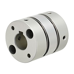


[Features]It is especially suitable for equipment that requires high precision and for use in clean environments.
Part Number
Configured Part Number is shown.
| Double Disc Type | Double Disc Type - Keywayed Bore (Keywayed Bore d1, d2) | |
| SCXW | SCXWK | |
 |  |
[ ! ] Recommended Tolerance of Shaft Diameter: h7.
[ ! ] Tolerances for d1 and d2 are values before slit machining.
[ ! ] The lateral, angular, and axial misalignment values shown are for each occurring individually. When multiple misalignments are occurring simultaneously, the allowable maximum value of each will be reduced to 1/2.
| Type | [A]Included Screw | [M] Material | [S] Surface Treatment | |||
| Main Body | Disc | Screw | Main Body | Screw | ||
| SCXW SCXWK | Hex Socket Head Cap Screw | Aluminum Alloy | Stainless steel | SCM435 | Clear Anodize Treatment | Black Oxide Film |
| Set Screw | ||||||
Specification Table
| Part Number | — | Shaft Bore Dia. d1 | — | Shaft Bore Dia. d2 |
| SCXW46 | — | 10 | — | 14 |
| SCXWK46 | — | 12 | — | 14 |
| Part Number | d1, d2 Selection (However, d1 ≤ d2) [ ! ] Only the dimensions in ( ) are selectable for keywayed bore type | D | d3 | L | ℓ | F | A | Clamp Screw | ||||||||||||||||
| Type | No. | M | Tightening Torque (N⋅m) | |||||||||||||||||||||
| SCXW | SCXWK | |||||||||||||||||||||||
| Double Disc Type SCXW Double Disc Type - Keywayed Bore SCXWK | 21 | 4 | 5 | 6 | (8) | 21 | 9.5 | 24.5 | 7 | 3.5 | 3 | 7 | M2.6 | 1.2 | ||||||||||
| 28 | 5 | 6 | (8) | (10) | 28 | 12 | 32 | 9 | 4 | 4 | 9.5 | M3 | 1.5 | |||||||||||
| 34 | 6 | (8) | (10) | (12) | (14) | 34 | 17 | 35 | 9.8 | 5 | 4.5 | 12 | M3 | 1.5 | ||||||||||
| 46 | 8 | (10) | (12) | (14) | 15 | 17 | 19 | 46 | 22 | 44 | 12.6 | 6 | 6 | 16.5 | M4 | 3.5 | ||||||||
| 55 | 12 | 14 | 15 | 17 | 19 | 20 | 22 | 24 | 25 | 54.5 | 26 | 55 | 16 | 7 | — | 20.5 | M5 | 7 | ||||||
| Part Number | Allowable Torque (N⋅m) | Allowable Angular Misalignment (°) | Allowable Lateral Misalignment (mm) | Static Torsional Spring Constant (N·m/rad) | Max. Rotational Speed (r/min) | Moment of Inertia (kg⋅m2) | Allowable Axial Misalignment (mm) | Compensation Factor Compensation Factor | Mass (g) | |
| Type | No. | |||||||||
| SCXW SCXWK | 21 | 1.2 | 1.0 | 0.10 | 900 | 10000 | 1.20 × 10⁻⁶ | ±0.20 | 1.5 | 18 |
| 28 | 1.6 | 1.2 | 0.15 | 3600 | 4.68 × 10⁻⁶ | 42 | ||||
| 34 | 4.0 | 1.5 | 0.20 | 5700 | 1.10 × 10⁻⁵ | 65 | ||||
| 46 | 10.0 | 0.25 | 14500 | 4.70 × 10⁻⁵ | ±0.30 | 151 | ||||
| 55 | 25.0 | 23000 | 1.19 × 10⁻⁴ | 260 | ||||||
Part Number
CAD Data download and 3D preview are not available because the part number has not yet been determined.
- *In order to open the CAD Data download and 3D preview screen, the part number must be fixed.
- Please confirm the part number from "Specification / Dimension"on the left side, and then perform the CAD Data Download / 3D Preview operation.
| Part Number |
|---|
| SCXW21-[4,5,6,8]-[4,5,6,8] |
| SCXW28-[5,6,8,10]-[5,6,8,10] |
| SCXW34-[6,8,10,12,14]-[6,8,10,12,14] |
| SCXW46-[8,10,12,14,15,17,19]-[8,10,12,14,15,17,19] |
| SCXW55-[12,14,15,17,19,20,22,24,25]-[12,14,15,17,19,20,22,24,25] |
| SCXWK21-8-8 |
| SCXWK28-[8,10]-[8,10] |
| SCXWK34-[8,10,12,14]-[8,10,12,14] |
| SCXWK46-[10,12,14]-[10,12,14] |
| Part Number | Standard Unit Price | Minimum order quantity | Volume Discount | Days to Ship | RoHS | Shaft Bore Dia. 1 d1 (or d) (Ø) | Shaft Bore Dia. 2 d2 (or d) (Ø) | O.D. (Ø) | Overall Length (mm) | Allowable Torque Range (N•m) | Allowable Torque (N•m) | Allowable Angular Misalignment (deg) | Allowable Lateral Misalignment (mm) | Allowable Lateral Misalignment Range (mm) | Allowable Axial Misalignment (mm) | Moment of Inertia (kg・m2) | Shaft Bore Shape |
|---|---|---|---|---|---|---|---|---|---|---|---|---|---|---|---|---|---|
- | 1 Piece(s) | 4 Day(s) or more | 10 | 4 ~ 8 | 4 ~ 8 | 21 | 24.5 | 1.01~3.00 | 1.2 | 1 | 0.1 | 0.02~0.2 | +0.20/-0.20 | 1.20×10⁻⁶ | Standard Bore | ||
- | 1 Piece(s) | 4 Day(s) or more | 10 | 5 ~ 10 | 5 ~ 10 | 28 | 32 | 1.01~3.00 | 1.6 | 1.2 | 0.15 | 0.02~0.2 | +0.20/-0.20 | 4.68×10⁻⁶ | Standard Bore | ||
- | 1 Piece(s) | 4 Day(s) or more | 10 | 6 ~ 14 | 6 ~ 14 | 34 | 35 | 3.01~5.00 | 4 | 1.5 | 0.2 | 0.02~0.2 | +0.20/-0.20 | 1.10×10⁻⁵ | Standard Bore | ||
- | 1 Piece(s) | 4 Day(s) or more | 10 | 8 ~ 19 | 8 ~ 19 | 46 | 44 | 5.01~10.00 | 10 | 1.5 | 0.25 | 0.21~0.40 | +0.30/-0.30 | 4.70×10⁻⁵ | Standard Bore | ||
- | 1 Piece(s) | 4 Day(s) or more | 10 | 12 ~ 25 | 12 ~ 25 | 54.5 | 55 | 20.01~50.00 | 25 | 1.5 | 0.25 | 0.21~0.40 | +0.30/-0.30 | 1.19×10⁻⁴ | Standard Bore | ||
- | 1 Piece(s) | 4 Day(s) or more | 10 | 8 | 8 | 21 | 24.5 | 1.01~3.00 | 1.2 | 1 | 0.1 | 0.02~0.2 | +0.20/-0.20 | 1.20×10⁻⁶ | Keywayed Bore d1, d2 side | ||
- | 1 Piece(s) | 4 Day(s) or more | 10 | 8 ~ 10 | 8 ~ 10 | 28 | 32 | 1.01~3.00 | 1.6 | 1.2 | 0.15 | 0.02~0.2 | +0.20/-0.20 | 4.68×10⁻⁶ | Keywayed Bore d1, d2 side | ||
- | 1 Piece(s) | 4 Day(s) or more | 10 | 8 ~ 14 | 8 ~ 14 | 34 | 35 | 3.01~5.00 | 4 | 1.5 | 0.2 | 0.02~0.2 | +0.20/-0.20 | 1.10×10⁻⁵ | Keywayed Bore d1, d2 side | ||
- | 1 Piece(s) | 4 Day(s) or more | 10 | 10 ~ 14 | 10 ~ 14 | 46 | 44 | 5.01~10.00 | 10 | 1.5 | 0.25 | 0.21~0.40 | +0.30/-0.30 | 4.70×10⁻⁵ | Keywayed Bore d1, d2 side |
Loading...
Specifications/Overview
| Keyway Dimension | |||||||||
 | Shaft bore diameter d1, d2 | b | t | Key Nominal Dim. b × h | Set Screw | ||||
| Standard Dimensions | Tolerance | Standard Dimensions | Tolerance | Size | Tightening Torque (N⋅m) | ||||
| 8·10 | 3 | ±0.0125 | 1.4 | +0.1 0 | 3 × 3 | M2 | 0.3 | ||
| 12 | 4 | ±0.0150 | 1.8 | 4 × 4 | M3 | 0.7 | |||
| 14 | 5 | 2.3 | 5 × 5 | M4 | 1.7 | ||||
App. Example
Basic Information
| Series Name | Disc | Application | For Servo Motors | Features | High Torsional Rigidity / High Torque Type / High Positioning Accuracy Type / Zero Backlash / Low Moment of Inertia / Clean Environment |
|---|---|---|---|---|---|
| Allowable Misalignment | Angular Misalignment / Eccentricity / Axial Misalignment | Max. Rotational Speed Range(r/min) | 1001~2000 | Product Category | Coupling Main Body |
| Max. Rotational Speed(r/min) | 10000 | Single/Double | Double |
Specification/Dimensions
-
Shaft Bore Dia. 1 d1 (or d)(Ø)
-
Shaft Bore Dia. 2 d2 (or d)(Ø)
-
O.D.(Ø)
-
Overall Length(mm)
-
Allowable Torque Range(N•m)
-
Allowable Torque(N•m)
-
Allowable Angular Misalignment(deg)
-
Allowable Lateral Misalignment(mm)
-
Allowable Lateral Misalignment Range(mm)
-
Shaft Bore Shape
-
type
- SCXW
- SCXWK
-
CAD
- 2D
- 3D
Days to Ship
-
- All
- 4 Day(s) or Less
Specify Alterations
- The specifications and dimensions of some parts may not be fully covered. For exact details, refer to manufacturer catalogs .
Additional Products in this Category
- Oldham Couplings - High Rigidity, Set Screw
- Jaw Couplings - Clamping
- Oldham Couplings Set Screw Type
- [Clean & Pack]Coupling - Slit, Set Screw, Short/Long
- Baumann flex MF
- MDW Flexible Coupling Disk Type
- K-7 Coupling SD Series
- Disc-Shaped Coupling, Clamping Long Type (Double Disc)
Complementary Products
-
 Rotary Shafts D Tolerance h9 (Cold-drawn) / h7 (Ground) / g6 (Ground) - One End Stepped and Threaded, One End Tapped
MISUMI Days to Ship : 5 Day(s) or more
-
 Bearings with Housings - Direct Mount, Compact
MISUMI Standard Price : MYR 52.12- Days to Ship : 2 Day(s) or more
-
 Angular Contact Bearings with Housings - Angular Contact Back-to-Back Combination + Deep Groove Ball Bearings, Flanged
MISUMI Standard Price : MYR 1,735.26- Days to Ship : 8 Day(s) or more


Customers Who Viewed This Item Also Viewed
-
 Disc Couplings Servo - Fine, for Servo Motors (High Rigidity)
MISUMI
Days to Ship : 4 Day(s) or more
-

-

-

-

-
 Disc Couplings - High Rigidity (O.D. 65), Keywayed Bore / Clamping, for Servo Motors
MISUMI
Days to Ship : 4 Day(s) or more
-

-
 Oldham Couplings - Large Shaft Diameter, Set Screw / Clamping / Spacers
MISUMI
Days to Ship : 6 Day(s) or more
-

-

-

-


Tech Support
- Factory Automation, Electronics, Tools, & MRO (Maintenance, Repair and Operations)
- Tel:(60) 3 7890 6399
- 9:00am - 6:00pm (Monday - Friday)
9:00am - 1:00pm (Saturday) - Technical Inquiry
- Credit Card
- Bank Transfer
Social Media
MISUMI Contact
Copyright © MISUMI Corporation All Rights Reserved.
How can we improve?
How can we improve?
While we are not able to respond directly to comments submitted in this form, the information will be reviewed for future improvement.
Customer Privacy Policy
Thank you for your cooperation.
While we are not able to respond directly to comments submitted in this form, the information will be reviewed for future improvement.
Please use the inquiry form.
Customer Privacy Policy